
You are currently browsing the tag archive for the ‘ERP’ tag.
 In the last two weeks, I have had mixed discussions related to PLM, where I realized the two different ways people can look at PLM. Are implementing PLM capabilities driven by a cost-benefit analysis and a business case? Or is implementing PLM capabilities driven by strategy providing business value for a company?
Most companies I am working with focus on the first option – there needs to be a business case.
 This observation is a pleasant passageway into a broader discussion started by Rob Ferrone recently with his article Money for nothing and PLM for free. He explains the PDM cost of doing business, which goes beyond the software’s cost. Often, companies consider the other expenses inescapable.
 At the same time, Benedict Smith wrote some visionary posts about the potential power of an AI-driven PLM strategy, the most recent article being PLM augmentation – Panning for Gold.
It is a visionary article about what is possible in the PLM space (if there was no legacy ☹), based on Robust Reasoning and how you could even start with LLM Augmentation for PLM “Micro-Tasks.
Interestingly, the articles from both Rob and Benedict were supported by AI-generated images – I believe this is the future: Creating an AI image of the message you have in mind.
![]() When you have digested their articles, it is time to dive deeper into the different perspectives of value and costs for PLM.
When you have digested their articles, it is time to dive deeper into the different perspectives of value and costs for PLM.
From a system to a strategy
 The biggest obstacle I have discovered is that people relate PLM to a system or, even worse, to an engineering tool. This 20-year-old misunderstanding probably comes from the fact that in the past, implementing PLM was more an IT activity – providing the best support for engineers and their data – than a business-driven set of capabilities needed to support the product lifecycle.
The System approach
Traditional organizations are siloed, and initially, PLM always had the challenge of supporting product information shared throughout the whole lifecycle, where there was no conventional focus per discipline to invest in sharing – every discipline has its P&L – and sharing comes with a cost.
 At the management level, the financial data coming from the ERP system drives the business. ERP systems are transactional and can provide real-time data about the company’s performance. C-level management wants to be sure they can see what is happening, so there is a massive focus on implementing the best ERP system.
In some cases, I noticed that the investment in ERP was twenty times more than the PLM investment.
 Why would you invest in PLM? Although the ERP engine will slow down without proper PLM, the complexity of PLM compared to ERP is a reason for management to look at the costs, as the PLM benefits are hard to grasp and depend on so much more than just execution.
See also my old 2015 article: How do you measure collaboration?
As I mentioned, the Cost of Non-Quality, too many iterations, time lost by searching, material scrap, manufacturing delays or customer complaints – often are considered inescapable parts of doing business (like everyone else) – it happens all the time..
The strategy approach
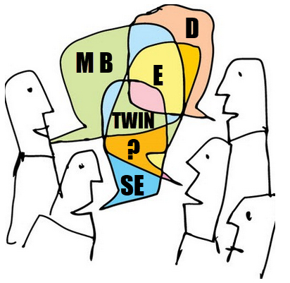
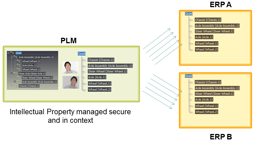
 It is clear that when we accept the modern definition of PLM, we should be considering product lifecycle management as the management of the product lifecycle (as Patrick Hillberg says eloquently in our Share PLM podcast – see the image at the bottom of this post, too).
When you implement a strategy, it is evident that there should be a long(er) term vision behind it, which can be challenging for companies. Also, please read my previous article: The importance of a (PLM) vision.
 I cannot believe that, although perhaps not fully understood, the importance of a data-driven approach will be discussed at many strategic board meetings. A data-driven approach is needed to implement a digital thread as the foundation for enhanced business models based on digital twins and to ensure data quality and governance supporting AI initiatives.
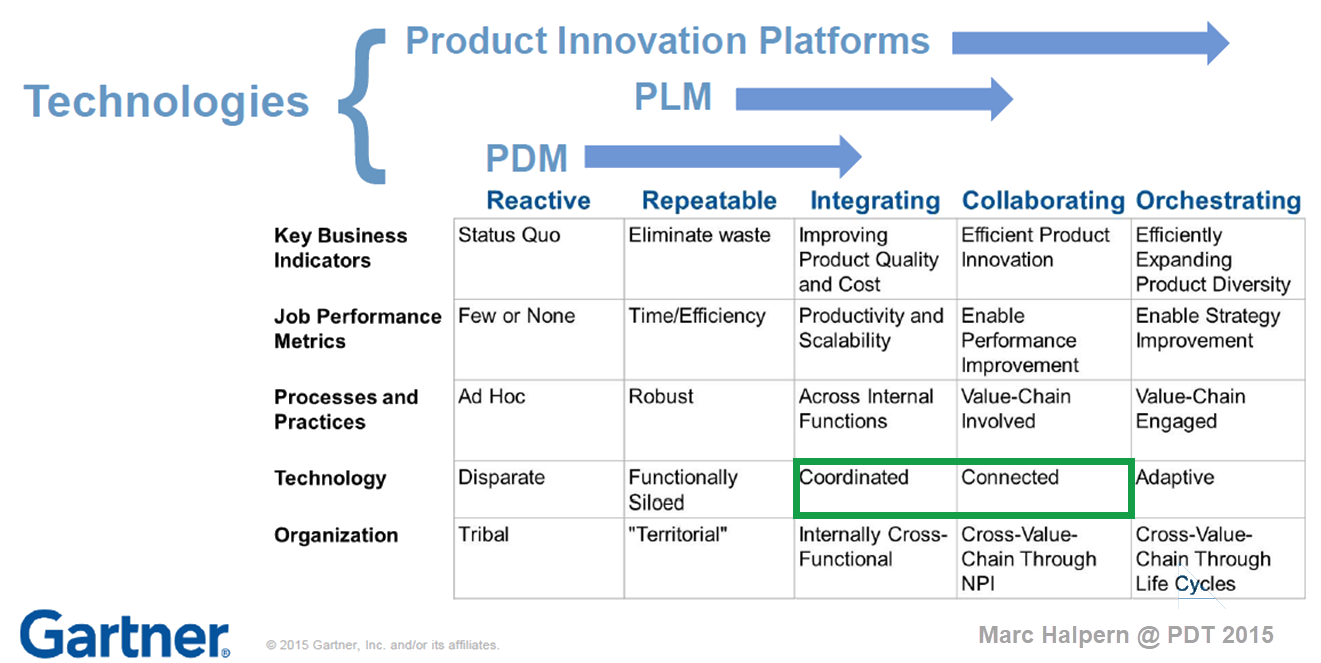
It is a process I have been preaching: From Coordinated to Coordinated and Connected.
We can be sure that at the board level, strategy discussions should be about value creation, not about reducing costs or avoiding risks as the future strategy.

Understanding the (PLM) value
The biggest challenge for companies is to understand how to modernize their PLM infrastructure to bring value.
* Step 1 is obvious. Stop considering PLM as a system with capabilities, but investigate how you transform your infrastructure from a collection of systems and (document) interfaces towards a federated infrastructure of connected tools.
![]() Note: the paradigm shift from a Single Source of Truth (in my system) towards a Nearest Source of Truth and a Single Source of Change.
Note: the paradigm shift from a Single Source of Truth (in my system) towards a Nearest Source of Truth and a Single Source of Change.
* Step 2 is education. A data-driven approach creates new opportunities and impacts how companies should run their business. Different skills are needed, and other organizational structures are required, from disciplines working in siloes to hybrid organizations where people can work in domain-driven environments (the Systems of Record) and product-centric teams (the System of Engagement). AI tools and capabilities will likely create an effortless flow of information within the enterprise.
* Step 3 is building a compelling story to implement the vision. Implementing new ways of working based on new technical capabilities requires also organizational change. If your organization keeps working similarly, you might gain some percentage of efficiency improvements.
 The real benefits come from doing things differently, and technology allows you to do it differently. However, this requires people to work differently, too, and this is the most common mistake in transformational projects.
Companies understand the WHY and WHAT but leave the HOW to the middle management.
 People are squeezed into an ideal performance without taking them on the journey. For that reason, it is essential to build a compelling story that motivates individuals to join the transformation. Assisting companies in building compelling story lines is one of the areas where I specialize.
Feel free to contact me to explore the opportunity for your business.
It is not the technology!
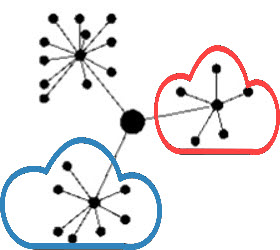
With the upcoming availability of AI tools, implementing a PLM strategy will no longer depend on how IT understands the technology, the systems and the interfaces needed.

As Yousef Hooshmand‘s above image describes, a federated infrastructure of connected (SaaS) solutions will enable companies to focus on accurate data (priority #1) and people creating and using accurate data (priority #1). As you can see, people and data in modern PLM are the highest priority.
Therefore, I look forward to participating in the upcoming Share PLM Summit on 27-28 May in Jerez.

It will be a breakthrough – where traditional PLM conferences focus on technology and best practices. This conference will focus on how we can involve and motivate people. Regardless of which industry you are active in, it is a universal topic for any company that wants to transform.
Conclusion
Returning to this article’s introduction, modern PLM is an opportunity to transform the business and make it future-proof. It needs to be done for sure now or in the near future. Therefore PLM initiatives should be considered from the value point first instead of focusing on the costs. How well are you connected to your management’s vision to make PLM a value discussion?

Enjoy the podcast – several topics discuss relate to this post.
 I am writing this post because one of my PLM peers recently asked me this question: “Is the BOM losing its position? He was in discussion with another colleague who told him:
“If you own the BOM, you own the Product Lifecycle”.
This statement made me think of ä recent post from Jan Bosch recent post: Product Development fallacy #8: the bill of materials has the highest priority.
 Software becomes increasingly an essential part of the final product, and combined with Jan’s expertise in software development, he wrote this article. I recommend reading the full post (4 min read) and next browse through the comments.
If you cannot afford these 10 minutes, here is my favorite quote from the article:
An excessive focus on the bill of materials leads to significant challenges for companies that are undergoing a digital transformation and adopting continuous value delivery. The lack of headroom, high coupling and versioning hell may easily cause an explosion of R&D expenditure over time.
Where did the BOM focus come from? A historical overview related to the rise (and fall) of the BOM.
In the beginning, there was the drawing.
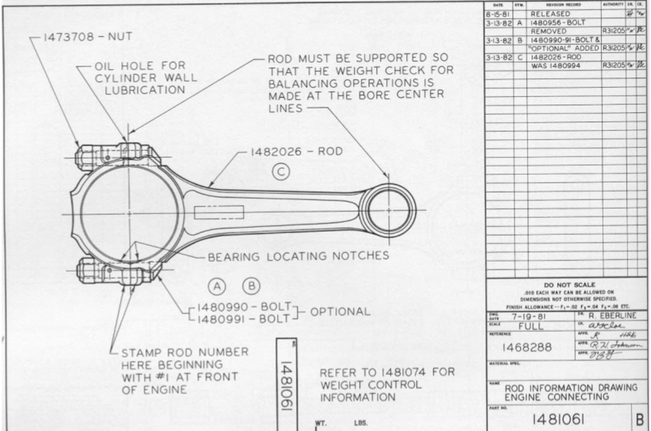 Before the era of computers, there was “THE drawing”, describing assemblies, subassemblies or parts. And on the drawing, you can find the parts list if relevant. This parts list was the first Bill of Material, describing the parts/materials shown on the drawing.
Next came MRP/ERP
 With the introduction of the MRP system (Material Requirement Planning), it was the first step that by using computers, people could collect the material requirements for one system as data and process.
Entering new materials/parts described on drawings was still a manual process, as well as referring to existing parts on the drawing. Reuse of parts was a manual process based on individual knowledge.
In the nineties, MRP evolved into ERP (Enterprise Resource Planning), which included the MRP part and added resource and manufacturing planning and financial reporting.
 The ERP system became the most significant IT system, the execution system of the company. As it was the first enterprise system implemented, it was the first moment we learned about implementation challenges – people change and budget overruns. However, as the ERP system brought visibility to the company’s execution, it became a “must-have” system for management.
The introduction of mainstream 2D CAD did not affect the company’s culture so much. Drawings became electronic drawings, and the methodology of the parts list on the drawing remained.
 Sometimes the interaction with the MRP/ERP system was enhanced by an interface – sending the drawing BOM to ERP. The advantage of the interface: no manual transfer of data reducing typos and BOM errors. The disadvantages at that time: relatively expensive (connectivity between systems was a challenge) and mostly one direction.
And then there was PDM.
 In parallel with the introduction of ERP systems, mainstream 3D CAD systems became affordable, particularly SolidWorks, Solid Edge and Inventor. These 3D CAD systems allow sharing of parts and assemblies in different products, and the PDM database was the first aid to support part reuse, versioning and standardization.
By extracting the parts from the assemblies and subassemblies, it was possible to generate a BOM structure in the PDM system to be transferred or typed into the ERP system. We did not talk about EBOM or MBOM then, as there was only one BOM in the ERP system, and the PDM system was a tool to feed the ERP system.
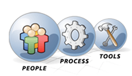
 Many companies still have based their processes on this approach. ERP (read SAP nowadays) is the central execution system, and PDM is an external system. You might remember the story and image from my previous post about people, processes and tools. The bad practice example: Asking the ERP system to provide a part number when starting to design a part.
And then products started to change.
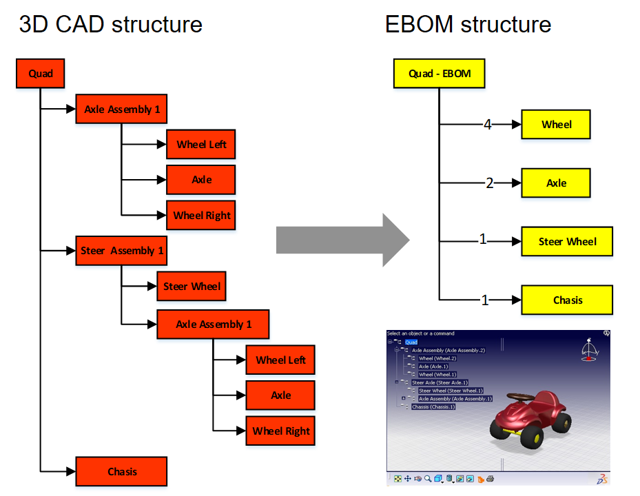
 In the early 2000s, I worked with SmarTeam to define the E&E (Electronics and Electrical) template. One of the new concepts was to synchronize all design data coming from different disciplines to a single BOM structure.
It was the time we started to talk about the EBOM. A type of BOM, as the structure to consolidate all the design data, was based on parts.
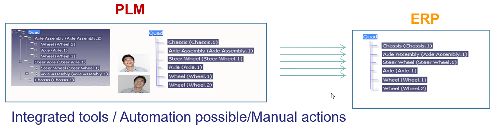
The EBOM, most of the time, reflects the design intent in logical groups and sending the relevant parts in the correct order to the ERP system was a favorite expensive customization for service providers. How to transfer an engineering BOM view to an ERP system that only understands the manufacturing view?
Note: not all ERP systems have the data model to differentiate between engineering parts and manufacturing parts
The image below illustrates the challenge and the customer’s perception. 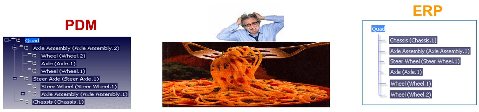
The automated link between the design side (EBOM) and manufacturing side (MBOM) was a mission impossible – too many exceptions for the (spaghetti) code.
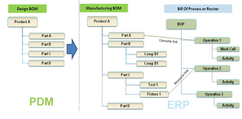
And then came the MBOM.
The identified issues connecting PDM and ERP led to the concept of implementing the MBOM in the PLM system. The MBOM in PLM is one of the characteristics of a PLM implementation compared to a PDM implementation. In a traditional PLM system, there is an interaction and connection between the EBOM and MBOM. EBOM parts should end up as MBOM parts. This interaction can be supported by automation, however, as it is in the same system, still leaving manual changes possible.
 The MBOM structure in PLM could then be the information structure to transfer to the ERP system; however, there is more, as Jörg W. Fischer wrote in his provoking post-Die MBOM muss weg (The MBOM must go). He rightly points out (in German) that the MBOM is not a structure on its own but a combination of different views based on Assembly Drawings, Process Planning and Material Requirements.
His conclusion:
Calling these structures, MBOM is trying to squeeze all three structures into one. That usually doesn’t work and then leads to much more emotional discussions in the project. It also costs a lot of money. It is, therefore, better not to use the term MBOM at all.
And indeed, just having an MBOM in your PLM system might help you to prepare some of the manufacturing steps, the needed resources and parts. The MBOM result still has to be localized at the local plant where the manufacturing takes place. And here, the systems used are the ERP system and the MES system.
The main advantage of having the MBOM in the PLM system is the direct relation between specification and manufacturing intent, allowing manufacturing engineering to work collaboratively with engineering in the same environment.
- The first benefit is fewer iterations and a shorter time to production, thanks to early interaction and manufacturing involvement in the engineering process.
- The second benefit is: product knowledge is centralized in a single system. Consolidating your Product Knowledge in ERP does not make sense due to global localization and the missing capabilities to manage the iterative engineering processes on non-existing parts.
And then came the SBOM, the xBOM
 Traditional PLM vendors and implementations kept using xBOM structures as placeholders for related specification data (mechanical designs, electrical, software deliverables, serialized products). Most of the time, related files.
 And with this approach, talking about digital thread, PLM systems also touch on the concepts of Configuration Management.
I will not go into the details here but look at the two images by clicking on them and see a similar mindset.
It is about the traceability of information in structures and systems. These structures work well in a relatively static and linear product development and delivery environment, as illustrated below:

Engineering change and release processes are based on managing the changes in different structures from the left to the right.
And then came software!
 Modern connected products are no longer mechanical products. The product’s functionality no longer depends on the mechanical properties but mainly on embedded electronics and software used. For example, look at the mechanical design of a telecom transmission tower – its behavior merely comes from non-mechanical components, and they can change over time. Still, the Bill of Material contains a lot of concrete and steel parts.
The ultimate example is comparing a Tesla (software on wheels) with a traditional car. For modern connected products, electronics and software need to be part of the solution. Software and electronics allow the product to be upgraded over time. Managing these products in the same manner as mechanical products is impossible, inefficient and therefore threatening your company’s future business.
I requote Jan Bosch:
An excessive focus on the bill of materials leads to significant challenges for companies that are undergoing a digital transformation and adopting continuous value delivery. The lack of headroom, high coupling and versioning hell may easily cause an explosion of R&D expenditure over time.
The model-based, connected enterprise
I will not solve the puzzle of the future in this post. You can read my observations in my series: The road to model-based and connected PLM. We need a new infrastructure with at least two modes. One that still serves as a System of Record, storing information in a traditional manner, like a Bill of Materials for the static parts, as not everyone and everything can be connected.
 In addition, we need various Systems of Engagement that enable close to real-time interaction between products (systems) and relevant stakeholders for the engagement scope(multidisciplinary / consumers).
Digital twins are examples of such environments. Currently, these Systems of Engagement often work disconnected from the System of Record due to the lack of understanding of how to connect. (standard connectors? / OSLC?)
Our mission is to explore, as I wrote in my post Time to split PLM and drop our mechanical mindset.
 And while I was finalizing this post, I read a motivating post from Jan Bosch again for all of you working on understanding and pushing the digital transformation in your eco-system.
The title: Be the protagonist of your life: 15 rules A starting point for more to come.
Conclusion
The BOM is no longer the master of the product lifecycle when it comes to managing connected products, where functionality mainly depends on software. BOM structures with related documents are just one of the extracted baselines from a data-driven, connected enterprise. This traditional PLM infrastructure requires other, non-BOM-driven structures to represent the actual status of a virtual or physical product.
The BOM is not dead, but there is more ………
Your thoughts?
 Those who have read my blog posts over the years will have seen the image to the left.
The people, processes and tools slogan points to the best practice of implementing (PLM and CM) systems.
Theoretically, a PLM implementation will move smoothly if the company first agrees on the desired processes and people involved before a system implementation using the right tools.
Too often, companies start from their historical landscape (the tools – starting with a vendor selection) and then try to figure out the optimal usage of their systems. The best example of this approach is the interaction between PDM(PLM) and ERP.
PDM and ERP
 Historically ERP was the first enterprise system that most companies implemented. For product development, there was the PDM system, an engineering tool, and for execution, there was the ERP system. Since ERP focuses on the company’s execution, the system became the management’s favorite.
The ERP system and its information were needed to run and control the company. Unfortunately, this approach has introduced the idea that the ERP system should also be the source of the part information, as it was often the first enterprise system for a company. The PDM system was often considered an engineering tool only. And when we talk about a PLM system, who really implements PLM as an enterprise system or was it still an engineering tool?
This is an example of Tools, Processes, and People – A BAD PRACTICE.
Imagine an engineer who wants to introduce a new part needed for a product to deliver. In many companies at the beginning of this century, even before starting the exercise, the engineer had to request a part number from the ERP system. This is implementation complexity #1.
Next, the engineer starts developing versions of the part based on the requirements. Ultimately the engineer might come to the conclusion this part will never be implemented. The reserved part number in ERP has been wasted – what to do?
It sounds weird, but this was a reality in discussions on this topic until ten years ago.
 Next, as the ERP system could only deal with 7 digits, what about part number reuse? In conclusion, it is a considerable risk that reused part numbers can lead to errors. With the introduction of the PLM systems, there was the opportunity to bridge the gap between engineering and manufacturing. Now it is clear for most companies that the engineer should create the initial part number.
Only when the conceptual part becomes approved to be used for the realization of the product, an exchange with the ERP system will be needed. Using the same part number or not, we do not care if we can map both identifiers between these environments and have traceability.
It took almost 10 years from PDM to PLM until companies agreed on this approach, and I am curious about your company’s status.
 Meanwhile, in the PLM world, we have evolved on this topic. The part and the BOM are no longer simple entities. Instead, we often differentiate between EBOM and MBOM, and the parts in those BOMs are not necessarily the same.
In this context, I like Prof. Dr. Jörg W. Fischer‘s framing:
EBOM is the specification, and MBOM is the realization.
(Leider schreibt Er viel auf Deutsch).
 An interesting discussion initiated by Jörg last week was again about the interaction between PLM and ERP. The article is an excellent example of how potentially mainstream enterprises are thinking. PLM = Siemens, ERP = SAP – an illustration of the “tools first” mindset before the ideal process is defined.
There was nothing wrong with that in the early days, as connectivity between different systems was difficult and expensive. Therefore people with a 20 year of experience might still rely on their systems infrastructure instead of data flow.
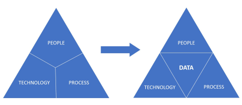
But enough about the bad practice – let’s go to people, processes, (data), and Tools
People, Processes, Data and Tools?
I got inspired by this topic, seeing this post two weeks ago from Juha Korpela, claiming:
Okay, so maybe a hot take, maybe not, but: the old “People, Process, Technology” trinity is one of the most harmful thinking patterns you can have. It leaves out a key element: Data.
His full post was quite focused on data, and I liked the ” wrapping post” from Dr. Nicolas Figay here, putting things more in perspective from his point of view. The reply made me think about how this discussion fits into the PLM digital transformation discussion. How would it work in the two major themes I use to explain the digital transformation in the PLM landscape?
For incidental readers of my blog, these are the two major themes I am using:
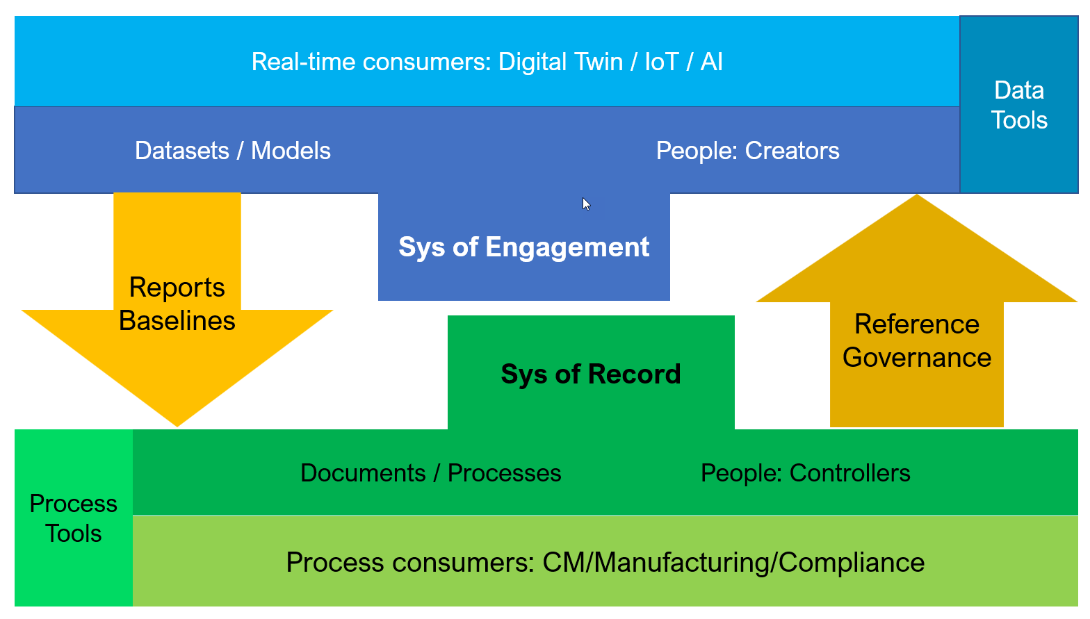
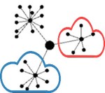
- From Coordinated to Connected, based on the famous diagram from Marc Halpern (image below). The coordinated approach based on documents (files) requires a particular timing (processes) and context (Bills of Information) – it is the traditional and current PLM approach for most companies. On the other hand, the Connected approach is based on connected datasets (here, we talk about data – not files). These connected datasets are available in different contexts, in real-time, to be used by all kinds of applications, particularly modeling applications. Read about it in the series: The road to model-based and connected PLM.

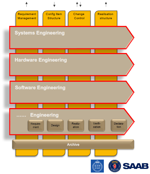
. - The need to split PLM, thinking in System(s) of Record and Systems of Engagement. (example below) The idea behind this split is driven by the observation that companies need various Systems of Record for configuration management, change management, compliance and realization. These activities sound like traditional PLM targets and could still be done in these systems. New in the discussion is the System of Engagement which focuses on a specific value stream in a digitally connected manner. Here data is essential.I discussed the coexistence of these two approaches in my post Time to Split PLM. A post on LinkedIn with many discussions and reshares illustrating the topic is hot. And I am happy to discuss “split PLM architectures” with all of you.

These two concepts discuss the processes and the tools, but what about the people? Here I came to a conclusion to complete the story, we have to imagine three kinds of people. And this will not be new. We have the creators of data, the controllers of data and the consumers of data. Let’s zoom in on their specifics.
A new representation?
 I am looking for a new simplifaction of the people, processes, and tools trinity combined with data; I got inspired by the work Don Farr did at Boeing, where he worked on a new visual representation for the model-based enterprise. You might have seen the image on the left before – click on it to see it in detail.
I wrote the first time about this new representation in my post: The weekend after CIMdata Roadmap / PDT Europe 2018
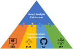
 Related to Configuration Management, Martijn Dullaart and Martin Haket have also worked on a diagram with their peers to depict the scope of CM and Impact Analysis. The image leads to the post with my favorite quote: Communication is merely an exchange of information, but connections tell the story.
Below I share my first attempt to combine the people, process and tools trinity with the concepts of document and data, system(s) of record and system(s) of engagement. Trying to build the story. Look if you recognize the aspects of the discussion above, and feel free to develop enhancements.
I look forward to your suggestions. Like the understanding that we have to split PLM thinking, as it impacts how we look at implementations.
Conclusion
Digital transformation in the PLM domain is forcing us to think differently. There will still be processes based on people collecting, interpreting and combining information. However, there will also be a new domain of connected data interpreted by models and algorithms, not necessarily depending on processes.
Therefore we need to work on new representations that can be used to tell this combined story. What do you think? How can we improve?
 As human beings, we believe in the truth. We claim the truth. During my holiday in Greece, the question was, did the Greek Prime Minister tell the truth about the internal spy scandal?
In general, we can say, politicians never speak the real truth, and some countries are trying to make sure there is only one single source of truth – their truth. The concept of a Single Source Of Truth (SSOT) is difficult to maintain in politics.
 On social media, Twitter and Facebook, people are claiming their truth. But unfortunately, without any scientific background, people know better than professionals by cherry-picking messages, statistics or even claiming non-existing facts.
Nicely described in The Dunning-Kruger effect. Unfortunately, this trend will not disappear.
If you want to learn more about the impact of social media, read this long article from The Atlantic: Why the Past 10 Years of American Life Have Been Uniquely Stupid. Although the article is about the US, the content is valid for all countries where social media are still allowed.
 The PLM and CM domain is the only place where people still rely on the truth defined by professionals. Manufacturing companies depend on reliable information to design, validate, manufacture and support their products. Compliance and safe products require an accurate and stable product definition based on approved information. Therefore, the concept of SSOT is crucial along the product lifecycle.
The importance may vary depending on the product type. The difference in complexity between an airplane and a plastic toy, for example. It is all about the risk and impact of a failure caused by the product.
During my holiday, the SSOT discussion was sparked on LinkedIn by Adam Keating, and the article starts with:
The “Single Source of Truth (SSOT)” wasn’t built for you. It was built for software vendors to get rich. Not a single company in the world has a proper SSOT.
 A bit provocative, as there is nothing wrong with software vendors being profitable. Profitability guarantees the long-time support of the software solution. Remember the PLM consolidation around 2006, when SmarTeam, Matrix One (Dassault), Agile and Eigner & Partner (Oracle) were acquired, disappeared or switched to maintenance mode.
Therefore it makes sense to have a profitable business model or perhaps a real open source business model.
 Still, the rest of the discussion was interesting, particularly in the LinkedIn comments. Adam mentioned the Authoritative Source of Truth (ASOT) as the new future. And although this concept becomes more and more visible in the PLM domain, I believe we need both. So, let’s have a look at these concepts.
Truth 1.0 – SSOT
 Historically, manufacturing companies stored the truth in documents, first paper-based, later in electronic file formats and databases.
The truth consists of drawings, part lists, specifications, and other types of information.
Moreover, the information is labeled with revisions and versions to identify the information.
By keeping track of the related information through documents or part lists with significant numbers, a person in the company could find the correct corresponding information at any stage of the lifecycle.
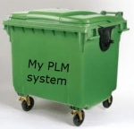
Later, by storing all the information in a central (PLM) system, the impression might be created that this system is the Single Source Of Truth. The system Adam Keating agitated against in his LinkedIn post.
 Although for many companies, the ERP has been the SSOT (and still is). All relevant engineering information was copied into the ERP system as attached files. Documents are the authoritative, legal pieces of information that a company shares with suppliers, authorities, or customers. They can reside in PLM but also in ERP. Therefore, you need an infrastructure to manage the “truth.”
Note: The Truth 1.0 story is very much a hardware story.
Even for hardware, ensuring a consistent single version of the truth for each product remains difficult. In theory, its design specifications should match the manufacturing definition. The reality, however, shows that often this is not the case. Issues discovered during the manufacturing process are fixed in the plant – redlining the drawing – is not always processed by engineering.
 As a result, Engineering and Manufacturing might have a different version of what they consider the truth.
The challenge for a service engineer in the field is often to discover the real truth. So the “truth” might not always be in the expected place – no guaranteed Single Source Of Truth.
Configuration Management is a discipline connected to PLM to ensure that the truth is managed so that as-specified, as-manufactured, and as-delivered information has been labeled and documented unambiguously. In other words, you could say Configuration Management(CM) is aiming for the Single Source Of Truth for a product.
 If you want to read more about the relation between PLM and CM – read this post: PLM and Configuration Management (CM), where I speak with Martijn Dullaart about the association between PLM and CM.
Martijn has his blog mdux.net and is the Lead Architect for Enterprise Configuration Management at our Dutch pride ASML. Martijn is also Chairperson I4.0 Committee IPX Congress.
Summarizing: The Single Source Of Truth 1.0 concept is document-based and should rely on CM practices, which require skilled people and the right methodology. In addition, some industries require Truth 1.0.
Others take the risk of working without solid CM practices, and the PLM system might create the impression of the SSOT; it will not be the case, even for only hardware.
Truth 2.0 – ASOT
 Products have become more complex, mainly due to the combination of electronics and software. Their different lifecycles and the speed of change are hard to maintain using the traditional PLM approach of SSOT.
It will be impossible to maintain an SSOT, particularly if it is based on documents.
As CM is the discipline to ensure data consistency, it is important to look into the future of CM. At the end of last year, I discussed this topic with 3 CM thought leaders. Martijn Dullaart, Maxime Gravel and Lisa Fenwick discussed with me what they believe the change would be. Read and listen here: The future of Configuration Management.
From the discussion, it became clear that managing all the details is impossible; still, you need an overreaching baseline to identify the severity and impact of a change along the product lifecycle.
New methodologies can be developed for this, as reliable data can be used in algorithms to analyze a change impact. This brings us to the digital thread. According to the CIMdata definition used in the A&D digital twin phase 2 position paper:
The digital thread provides the ability for a business to have an Authoritative Source of Truth(ASOT), which is information available and connected in a core set of the enterprise systems across the lifecycle and supplier networks
The definition implies that, in the end, a decision is made on data from the most reliable, connected source. There might be different data in other locations. However, this information is less reliable. Updating or fixing this information does not make sense as the effort and cost of fixing will be too expensive and give no benefit.
Obviously, we need reliable data to implement the various types of digital twins.
 As I am intrigued by the power of the brain – its strengths and weaknesses – the concept of ASOT can also be found in our brains. Daniel Kahneman’s book, Thinking Fast and Slow talks about the two systems/modes our brain uses. The Fast one (System 1 – low energy usage) could be the imaginary SSOT, whereas the Slow one (System 2 – high energy required) is the ASOT. The brain needs both, and I believe this is the same in our PLM domain.
A new PLM Paradigm
In this context, there is a vivid discussion about the System of Record and Systems of Engagement. I wrote about it in June (post: A new PLM paradigm); other authors name it differently, but all express a similar concept. Have a look at these recent articles and statements from:
| Author | Link to content |
|
Authentise
|
The challenge of cross-discipline collaboration ……. |
|
Beyond PLM
|
When is the right time to change your PLM system + discussion |
|
Colab
|
The Single Source Of Truth wasn’t built for you ……. |
|
Fraunhofer institute
|
Killing the PLM Monolith – the Emergence of cloud-native System Lifecycle Management (SysLM) |
|
SAAB Group
|
Don’t mix the tenses. Managing the Present and the Future in an MBSE context |
|
Yousef Hooshmand
|
From a Monolithic PLM Landscape to a Federated Domain and Data Mesh |
If you want to learn more about these concepts and discuss them with some of the experts in this domain, come to the upcoming PLM Roadmap PTD Europe conference on 18-19 October in Gothenburg, Sweden. Have a look at the final agenda here
Register before September 12 to benefit from a 15 % Early Bird discount, which you can spend for the dinner after day 1. I look forward to discussing the SSOT/ASOT topics there.
Conclusion
The Single Source Of Truth (SSOT) and the Authoritative Source of Truth (ASOT) are terms that illustrate the traditional PLM paradigm is changing thanks to digitization and connected stakeholders. The change is in the air. Now, the experience has to come. So be part of the change and discuss with us.
 In March 2018, I started a series of blog posts related to model-based approaches. The first post was: Model-Based – an introduction. The reactions to these series of posts can be summarized in two bullets:
- Readers believed that the term model-based was focusing on the 3D CAD model. A logical association as PLM is often associated with 3D CAD-model data management (actually PDM), and in many companies, the 3D CAD model is (yet) not a major information carrier/
- Readers were telling me that a model-based approach is too far from their day-to-day life. I have to agree here. I was active in some advanced projects where the product’s behavior depends on a combination of hardware and software. However, most companies still work in a document-driven, siloed discipline manner merging all deliverables in a BOM.
 More than 3 years later, I feel that model-based approaches have become more and more visible for companies. One of the primary reasons is that companies start to collaborate in the cloud and realize the differences between a coordinated and a connected manner.
Initiatives as Industry 4.0 or concepts like the Digital Twin demand a model-based approach. This post is a follow-up to my recent post, The Future of PLM.
History has shown that it is difficult for companies to change engineering concepts. So let’s first look back at how concepts slowly changed.
The age of paper drawings
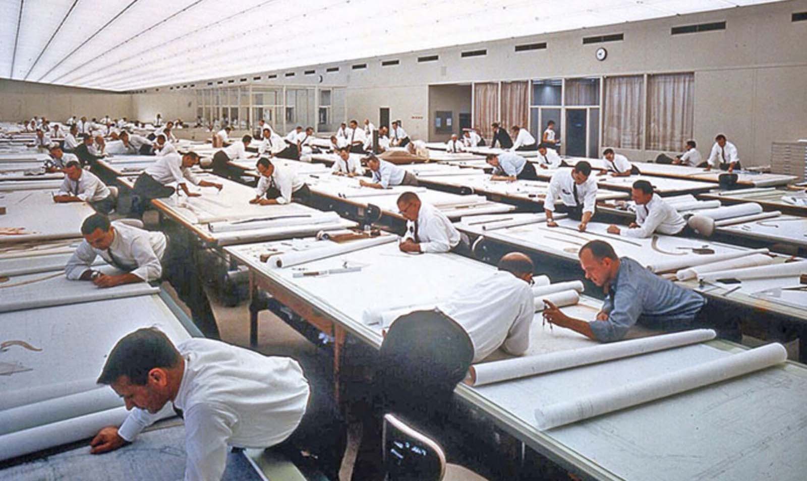 In the sixties of the previous century, the drawing board was the primary “tool” to specify a mechanical product. The drawing on its own was often a masterpiece drawn on special paper, with perspectives, details, cross-sections.
All these details were needed to transfer the part or assembly information to manufacturing. The drawing set should contain all information as there were no computers.
 Making a prototype was, depending on the complexity of the product, the interpretation of the drawings and manufacturability of a product, not always that easy. After a first release, further modifications to the product definition were often marked on the manufacturing drawings using a red pencil. Terms like blueprint and redlining come from the age of paper drawings.
There are still people talking nostalgically about these days as creating and interpreting drawings was an important skill. However, the inefficiencies with this approach were significant.
- First, updating drawings because there was redlining in manufacturing was often not done – too much work.
- Second, drawing reuse was almost impossible; you had to start from scratch.
- Third, and most importantly, you needed to be very skilled in interpreting a drawing set. In particular, when dealing with suppliers that might not have the same skillset and the knowledge of which drawing version was actual.
 However, paper was and still is the cheapest neutral format to distribute designs. The last time I saw companies still working with paper drawings was at the end of the previous century.
Curious to learn if they are now extinct?
The age of electronic drawings (CAD)
With the introduction of AutoCAD and personal computers around 1982, more companies started to look into drafting with the computer. There was already the IBM drafting system in 1965, but it was Autodesk that pushed the 2D drafting business with their slogan:
“80 percent of the functionality for 20 percent of the price (Autodesk 1982)”
A little later, I started to work for an Autodesk distributor/reseller. People would come to the showroom to see how a computer drawing could be plotted in the finest quality at the end. But, of course, the original draftsman did not like the computer as the screen was too small.
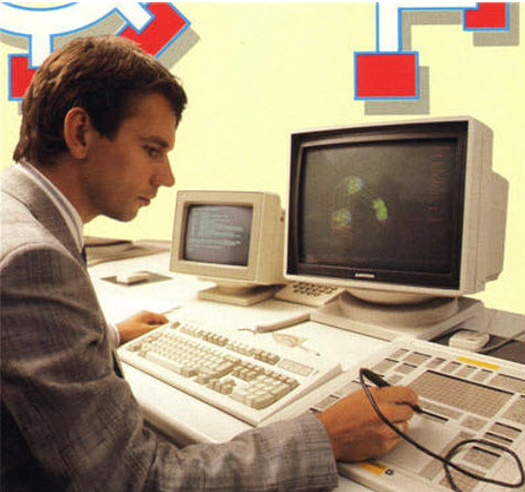 However, the enormous value came from making changes, the easy way of sharing drawings and the ease of reuse. The picture on the left is me in 1989, demonstrating AutoCAD with a custom-defined tablet and PS/2 computer.
The introduction of electronic drawings was not a disruption, more optimization of the previous ways of working.
The exchange with suppliers and manufacturing could still be based on plotted drawings – the most neutral format. And thanks to the filename, there was better control of versions between all stakeholders.
Aren’t we all happy?
The introduction of mainstream 3D CAD
 In 1995, 3D CAD became available for the mid-market, thanks to SolidWorks, Solid Edge and a little later Inventor. Before that working with 3D CAD was only possible for companies that could afford expensive graphic stations, provided by IBM, Silicon Graphics, DEC and SUN. Where are they nowadays? The PC is an example of disruptive innovation, purely based on technology. See Clayton Christensen’s famous book: The Innovator’s Dilemma.
The introduction of 3D CAD on PCs in the mid-market did not lead directly to new ways of working. Designing a product in 3D was much more efficient if you mastered the skills. 3D brought a better understanding of the product dimensions and shape, reducing the number of interpretation errors.
 Still, (electronic) drawings were the contractual deliverable when interacting with suppliers and manufacturing. As students were more and more trained with the 3D CAD tools, the traditional art of the draftsman disappeared.
3D CAD introduced some new topics to solve.
- First of all, a 3D CAD Assembly in the system was a collection of separate files, subassemblies, parts, and drawings that relate to each other with a specific version. So how to ensure the final assembly drawings were based on the correct part revisions? Companies were solving this by either using intelligent filenames (with revisions) or by using a PDM system where the database of the PDM system managed all the relations and their status.
- The second point was that the 3D CAD assembly also introduced a new feature, the product structure, or the “Bill of Materials”. This logical structure of the assembly up resembled a lot of the Bill of Material of the product. You could even browse deeper levels, which was not the case in the traditional Bill of Material on a drawing.
Note: The concept of EBOM and MBOM was not known in most companies. People were talking about the BOM as a one-level definition of parts or subassemblies in the assembly. See my Where is the MBOM? Post from July 2008 when this topic was still under discussion.
- The third point that would have a more significant impact later is that parts and assemblies could be reused in other products. This introduced the complexity of configuration management. For example, a 3D CAD part or assembly file could contain several configurations where only one configuration would be valid for the given product. Managing this in the 3D CAD system lead to higher productivity of the designer, however downstream when it came to data management with PDM systems, it became a nightmare.

I experienced these issues a lot when discussing with companies and implementers, mainly the implementation of SmarTeam combined with SolidWorks and Inventor. Where to manage the configuration constraints? In the PDM system or inside the 3D CAD system.
These environments were not friends (image above), and even if they came from the same vendor, it felt like discussing with tribes.
The third point also covered another topic. So far, CAD had been the first step for the detailed design of a product. However, companies now had an existing Bill of Material in the system thanks to the PDM systems. It could be a Bill of Material of a sub-assembly that is used in many other products.
Configuring a product no longer started from CAD; it started from a Product or Bill of Material structure. Sales and Engineers identified the changes needed on the BoM, keeping as much as possible released information untouched. This led to a new best practice.
The item-centric approach
 Around 2005, five years after introducing the term Product Lifecycle Management, slowly, a new approach became the standard. Product Lifecycle Management was initially introduced to connect engineering and manufacturing, driven by the automotive and aerospace industry.
It was with PLM that concepts as EBOM and MBOM became visible.
In particular, the EBOM was closely linked to engineering practices, i.e., modularity and reuse. The EBOM and its related information represented the product as it was specified. It is essential to realize that the parts in the EBOM could be generic specified purchase parts to be resolved when producing the product or that the EBOM contained Make-parts specified by drawings.
At that time, the EBOM was often used as the foundation for the ERP system – see image above. The BOM was restructured and organized according to the manufacturing process specifying materials and resources needed in the ERP system. Therefore, although it was an item-like structure, this BOM (the MBOM) always had a close relation to the Bill of Process.
For companies with a single manufacturing site, the notion of EBOM and MBOM was not that big, as the ERP system would be the source of the MBOM. However, the complexity came when companies have several manufacturing sites. That was when a generic MBOM in the PLM system made more sense to centralize all product information in a single system.
The EBOM-MBOM approach has become more and more a standard practice since 2010. As a result, even small and medium-sized enterprises realized a need to manage the EBOM and the MBOM.
There were two disadvantages introduced with this EBOM-MBOM approach.
- First, the EBOM and the MBOM as information structures require a lot of administrative maintenance if information needs to be always correct (and that is the CM target). Some try to simplify this by keeping the EBOM part the same as the MBOM part, meaning the EBOM specification already targets a single supplier or manufacturer.
- The second disadvantage of making every item in the BOM behave like a part creates inefficiencies in modern environments. Products are a mix of hardware(parts) and software(models/behavior). This BOM-centric view does not provide the proper infrastructure for a data-driven approach as part specifications are still done in drawings. We need 3D annotated models related to all kinds of other behavior and physical models to specify a product that contains hard-and software.
 A new paradigm is needed to manage this mix efficiently, the enabling foundation for Industry 4.0 and efficient Digital Twins; there is a need for a model-based approach based on connected data elements.
More next week.
Conclusion
| The age of paper drawings | 1960 – now dead |
| The age of electronic drawings | 1982 – potentially dead in 2030 |
| The mainstream 3D CAD | 1995 – to be evolving through MBD and MBSE to the future – not dead shortly |
| Item-centric approach | 2005 – to be evolving to a connected model-based approach – not dead shortly |
In the last two weeks, three events were leading to this post.
 First, I read John Stark’s recent book Products2019. A must-read for anyone who wants to understand the full reach of product lifecycle related activities. See my recent post: Products2019, a must-read if you are new to PLM
Afterwards, I talked with John, discussing the lack of knowledge and teaching of PLM, not to be confused by PLM capabilities and features.
 Second, I participated in an exciting PI DX USA 2020 event. Some of the sessions and most of the roundtables provided insights to me and, hopefully, many other participants. You can get an impression in the post: The Weekend after PI DX 2020 USA.
A small disappointment in that event was the closing session with six vendors, as I wrote. I know it is evident when you put a group of vendors in the arena, it will be about scoring points instead of finding alignment. Still, having criticism does not mean blaming, and I am always open to having a dialogue. For that reason, I am grateful for their sponsorship and contribution.
Oleg Shilovitsky mentioned cleverly that this statement is a contradiction.
![]()
“How can you accuse PLM vendors of having a limited view on PLM and thanking them for their contribution?”
I hope the above explanation says it all, combined with the fact that I grew up in a Dutch culture of not hiding friction, meanwhile being respectful to others.
We cannot simplify PLM by just a better tool or technology or by 3D for everybody. There are so many more people and processes related to product lifecycle management involved in this domain if you want a real conference, however many of them will not sponsor events.
 It is well illustrated in John Stark’s book. Many disciplines are involved in the product lifecycle. Therefore, if you only focus on what you can do with your tool, it will lead to an incomplete understanding.
If your tool is a hammer, you hope to see nails everywhere around you to demonstrate your value
 The thirds event was a LinkedIn post from John Stark – 16 groups needing Product Lifecycle Knowledge, which for me was a logical follow-up on the previous two events. I promised John to go through these 16 groups and provide my thoughts.
Please read his post first as I will not rewrite what has been said by John already.
CEOs and CTOs
 John suggested that they should read his book, which might take more than eight hours. CEOs and CTOs, most of the time, do not read this type of book with so many details, so probably mission impossible.
They want to keep up with the significant trends and need to think about future business (model).
New digital and technical capabilities allow companies to move from a linear, coordinated business towards a resilient, connected business. This requires exploring future business models and working methods by experimenting in real-life, not Proof of Concept. Creating a learning culture and allowing experiments to fail is crucial, as you only learn by failing.
CDO, CIOs and Digital Transformation Executives
 They are the crucial people to help the business to imagine what digital technologies can do. They should educate the board and the business teams about the power of having reliable, real-time data available for everyone connected. Instead of standardizing on systems and optimizing the siloes, they should assist and lead in new infrastructure for connected services, end-to-end flows delivered on connected platforms.
These concepts won’t be realized soon. However, doing nothing is a big risk, as the traditional business will decline in a competitive environment. Time to act.
Departmental Managers
 These are the people that should worry about their job in the long term. Their current mission might be to optimize their department within its own Profit & Loss budget. The future is about optimizing the information flow for the whole value chain, including suppliers and customers.
I wrote about it in “The Middle Management Dilemma.” Departmental Managers should become more team leaders inspiring and supporting the team members instead of controlling the numbers.
Products Managers
 This is a crucial role for the future, assuming a product manager is not only responsible for the marketing or development side of the product but also gets responsibility for understanding what happens with the product during production and sales performance. Understanding the full lifecycle performance and cost should be their mission, supported by a digital infrastructure.
Product Developers
They should read the book Products2019 to be aware there is so much related to their work. From this understanding, a product developer should ask the question:
“What can I do better to serve my internal and external customers ?”
 This question will no arise in a hierarchical organization where people are controlled by managers that have a mission to optimize their silo. Product Developers should be trained and coached to operate in a broader context, which should be part of your company’s mission. Too many people complain about usability in their authoring and data management systems without having a holistic understanding of why you need change processes and configuration management.
Product Lifecycle Management (PLM) deployers
Here I have a little bit of the challenge that this might be read as PLM-system users. However, it should be clear that we mean here people using product data at any moment along the product lifecycle, not necessarily in a single system.
This is again related to your company’s management culture. In the ideal world, people work with a purpose and get informed on how their contribution fits the company’s strategy and execution.

Unfortunately, in most hierarchical organizations, the strategy and total overview get lost, and people become measured resources.
New Hires and others
John continues with five other groups within the organization. I will not comment on them, as the answers are similar to the ones above – it is about organization and culture.
Educators and Students
 This topic is very close to my heart, and one of the reasons I continue blogging about PLM practices. There is not enough attention to product development methodology or processes. Engineers can get many years of education in specific domains, like product design principles, available tools and technologies, performing physical and logical simulations.
Not so much time is spent on educating current best practices, business models for product lifecycle management.
 Check in your country how many vendor-independent methodology-oriented training you can find. Perhaps the only consistent organization I know is CIMdata, where the challenge is that they deliver training to companies after students have graduated. It would be great if education institutes would embed serious time for product lifecycle management topics in their curriculum. The challenge, of course, the time and budget needed to create materials and, coming next, prioritizing this topic on the overall agenda.
 I am happy to participate to a Specialized Master education program aiming at the Products and Buildings Digital Engineering Manager (INGENUM). This program organized by Arts Et Metiers in France helps create the overview for understanding PLM and BIM – in the French language as before COVID-19 this was an on-site training course in Paris.
Hopefully, there are more institutes offering PLM eductation – feel free to add them in the comments of this post.
Consultants, Integrators and Software Company Employees
 Of course, it would be nice if everyone in these groups understands the total flow and processes within an organization and how they relate to each other. Too often, I have seen experts in a specific domain, for example, a 3D CAD-system having no clue about revisioning, the relation of CAD to the BOM, or the fundamentals of configuration management.
Consultants, Integrators and Software Company Employees have their own challenges as their business model is often looking for specialized skills they can sell to their clients, where a broader and general knowledge will come from experience on-the-job.
And if you are three years working full-time on a single project or perhaps work in three projects, your broader knowledge does not grow fast. You might become the hammer that sees nails everywhere.
For that reason, I recommend everyone in my ecosystem to invest your personal time to read related topics of interest. Read LinkedIn-posts from others and learn to differentiate between marketing messages and people willing to share experiences. Don’t waste your time on the marketing messages and react and participate in the other discussions. A “Like” is not enough. Ask questions or add your insights.
 In the context of my personal learning, I mentioned that I participated in the DigitalTwin-conference in the Netherlands this week. Unfortunately, due to the partial lockdown, mainly a virtual event.
I got several new insights that I will share with you soon. An event that illustrated Digital Twin as a buzzword might be hype, however several of the participants illustrated examples of where they applied or plan to apply Digital Twin concepts. A great touch with reality.
 Another upcoming conference that will start next week in the PLM Roadmap 2020 – PDT conference. The theme: Digital Thread—the PLM Professionals’ Path to Delivering Innovation, Efficiency, and Quality is not a marketing theme as you can learn from the agenda. Step by step we are learning here from each other.
Conclusion
John Stark started with the question of who should need Product Lifecycle Knowledge. In general, Knowledge is power, and it does not come for free. Either by consultancy, reading or training. Related to Product Lifecycle Management, everyone must understand the bigger picture. For executives as they will need to steer the company in the right direction. For everyone else to streamline the company and enjoy working in a profitable environment where you contribute and can even inspire others.
An organization is like a human body; you cannot have individual cells or organs that optimize themselves only – we have a name for that disease. Want to learn more? Read this poem: Who should be the boss?
I believe we are almost at the end of learning from the past. We have seen how, from an initial serial CAD-driven approach with PDM, we evolved to PLM-managed structures, the EBOM and the MBOM. Or to illustrate this statement, look at the image below, where I use a Tech-Clarity image from Jim Brown.
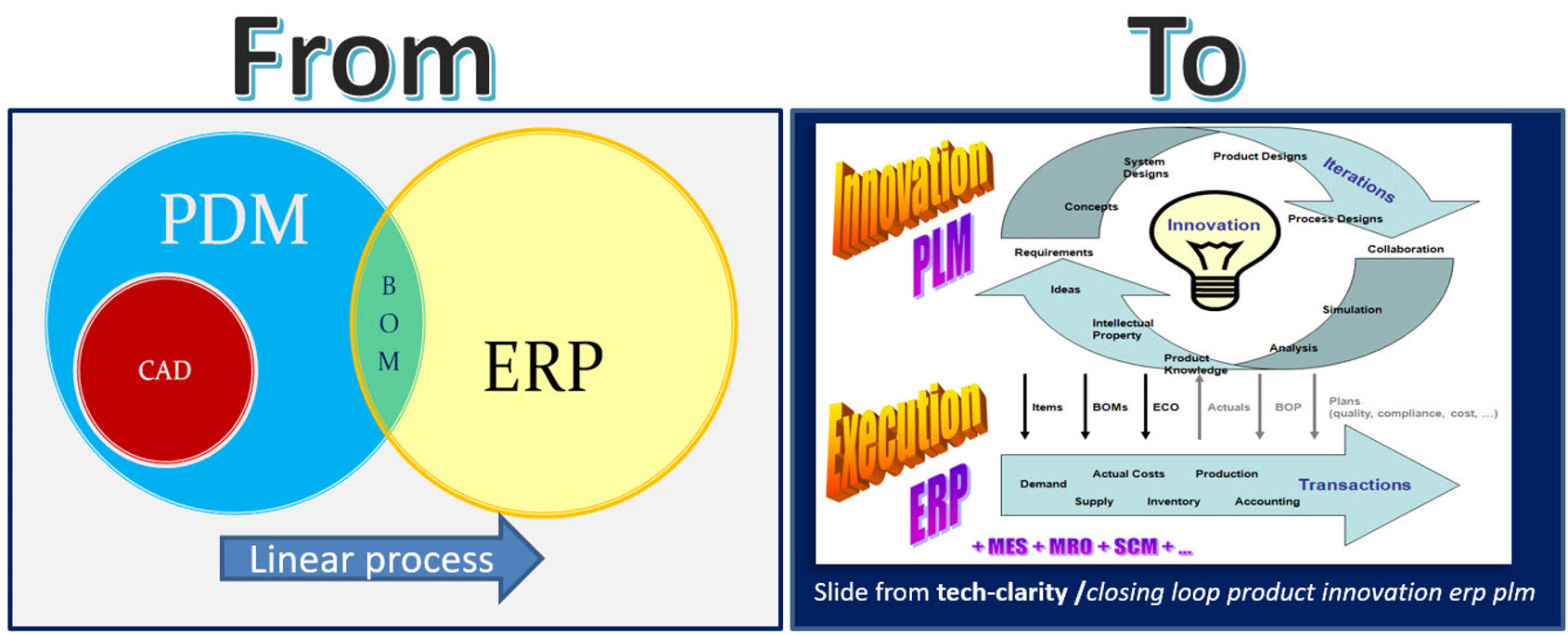
The image on the right describes perfectly the complementary roles of PLM and ERP. The image on the left shows the typical PDM-approach. PDM feeding ERP in a linear process. The image on the right, I believe it is from 2004, shows the best practice before digital transformation. PLM is supporting product innovation in an iterative approach, pushing released information to ERP for execution.
 As I think in images, I like the concept of a circle for PLM and an arrow for ERP. I am always using those two images in discussions with my customers when we want to understand if a particular activity should be in the PLM or ERP-domain.
Ten years ago, the PLM-domain was conceptually further extended by introducing support for products in operations and service. Similar to the EBOM (engineering) and the MBOM (manufacturing), the SBOM (service) was introduced to support product information for products in operation. In theory a full connected cicle.
Asset Lifecycle Management
At the same time, I was promoting PLM-practices for owners/operators to enhance Asset Lifecycle Management. My first post from June 2010 was called: PLM for Asset Lifecycle Management and Asset Development introduces this approach.
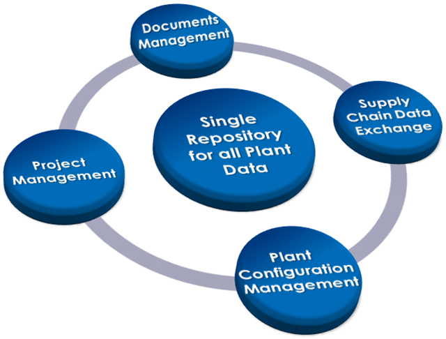 Conceptually the SBOM and Asset Lifecycle Management have a lot in common. There is a design product, in this case, an asset (plant, machine) running in the field, and we need to make sure operators have the latest information about the asset. And in case of asset changes, which can be a maintenance operation, a repair or complete overall, we need to be sure the changes are based on the correct information from the as-built environment. This requires full configuration management.
Asset changes can be based on extensive projects that need to be treated like new product development projects, with a staged approach that can take weeks, months, sometimes years. These activities are typical activities performed in PLM-systems, not in MRO-systems that are designed to manage the actual operation. Again here we see the complementary roles of PLM (iterative) and MRO (execution).
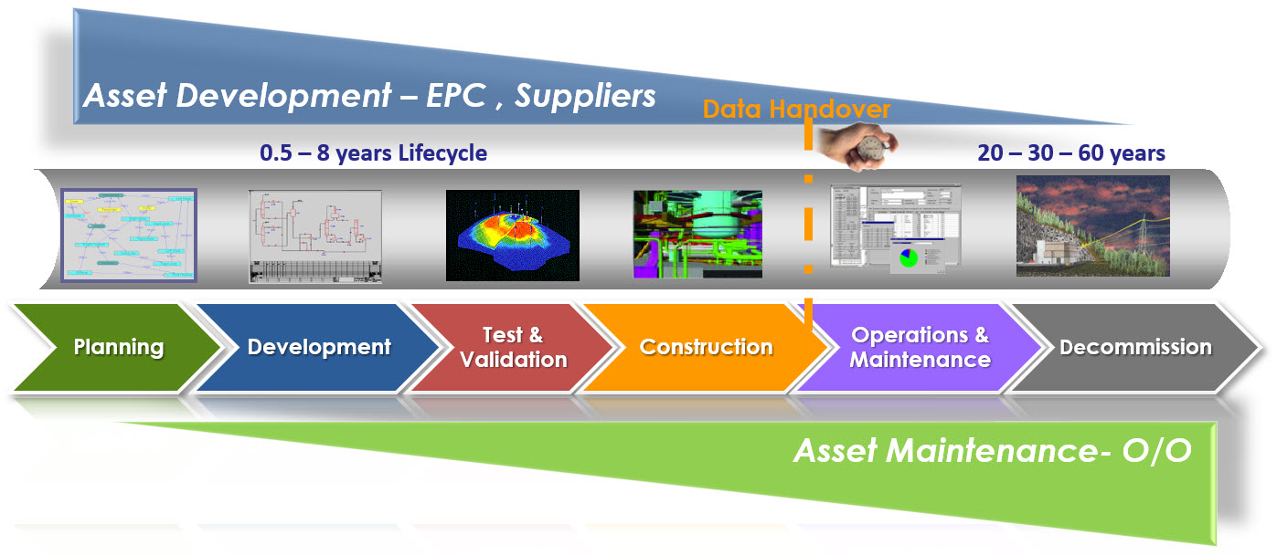
Since 2008, I have worked a lot in this environment, mainly in the nuclear and process industry. If you want to learn more about this aspect of PLM, I recommend looking at the PLMpartner website, where Bjørn Fidjeland, in cooperation with SharePLM, published a course on Plant Information Management. We worked together in several projects and Bjørn has done a great effort to describe the logical model to be used instead of a function-feature story.
Ten years ago, we were not calling this concept the “Digital Twin,” as the aim was to provide end-to-end support of asset information from engineering, procurement, and construction towards operation in a coordinated manner. The breaking point in the relation between the EPCs and Owner/Operators is the data-handover – how much of your IP can/do you expose and what is needed. Nowadays, we would call striving for end-to-end data continuity the Digital Thread.
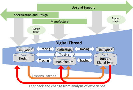
Hot from the press in this context, CIMdata just published a commentary Managing the Digital Thread in Global Value Chains describing Eurostep’s ShareAspace capabilities and experiences in managing an end-to-end information flow (Digital Thread) in a heterogeneous environment based on exchange standards like ISO 10303-239 PLCS. Their solution is based on what I consider a more modern approach for managing digital continuity compared to the traditional approach I described before. Compare the two images in this paragraph. The first image represents the old/current way with a disconnected handover, the second represents ShareAspace connected approach based on a real digital thread.
The Service BOM
As discussed with Asset Lifecycle Management, there is a disconnect between the engineering disciplines and operations in the field, looking from the point of view of an Asset owner/operator.
Now when we look from the perspective of a manufacturing company that produces assets to be serviced, we can identify a different dataflow and a new structure, the Service BOM (SBOM).
 The SBOM provides information on how a product needs to be serviced. What are the parts that require service, and what are the service kits that are possible for that product? For that reason, service engineering should be done in parallel to product engineering. When designing a product, the engineer needs to identify which the wearing parts (always require service in time) and which parts might be serviceable.
There are different ways to look at the SBOM. Conceptually, the SBOM could be created in close relation with the EBOM. At the moment you define your product, you also should specify how the product will be serviced. See the image below

From this example, it is clear that part standardization and modularization have a considerable benefit for services downstream. What if you have only one serviceable part that applies to many products? The number of parts to have in stock will be strongly reduced instead of having many similar parts that only fit in a single product?
 Depending on the type of product, the SBOM can be generic, serving many products in the field. In that case, the company has to deal with catalogs, to be defined in PLM. Or the SBOM can be aligned with the As-Built of a capital product in the field. In that case, the concepts of Asset Lifecycle Management apply. Click on the image to see a clear picture.
![]() The SBOM on its own, in such an environment, will have links to specific documents, service instructions, operating manuals.
The SBOM on its own, in such an environment, will have links to specific documents, service instructions, operating manuals.
If your PLM-system allows it, extending the EBOM and MBOM with an SBOM is not a complex effort. What is crucial to understand is that the SBOM has its own lifecycle, which can even last longer than the active product sold. So sometimes, manufacturing specifications, related to service parts need to be maintained too, creating a link between the SBOM and potential MBOM(s).
ECM = Enterprise Change Management
When I discussed ECM in my previous post in the context of Engineering Change Management, I got the feedback that nowadays, everyone talks about Enterprise Change Management. Engineering Change Management is old school.
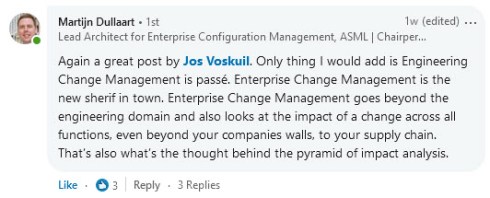
In the past, and even in a 2014 benchmark, a customer had two change management systems. One in PLM and one in ERP, and companies were looking into connecting these two processes. Like the BOM-interaction between PLM and ERP, this is technology-wise, never a real problem.
 The real problem in such situations was to come to a logical flow of events. Many times the company insisted that every change should start from the ERP-system as we like to standardize. This means that even an engineering change had to be registered first in the ERP-system
Luckily the reach of PLM has grown. PLM is no longer the engineering tool (IT-system thinking). PLM has become the information backbone for product information all along the product lifecycle. Having the MBOM and SBOM available through a PLM-infrastructure allows organizations to streamline their processes.
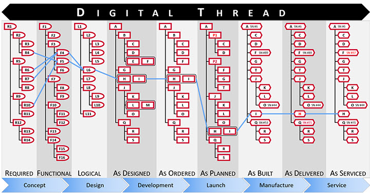
Aras – digital thread through connected structures
And in this modern environment, enterprise change management might take place mostly in a PLM-infrastructure. The PLM-infrastructure providing a digital thread, as the Aras picture above illustrates, provides the full traceability to support configuration management.
However, we still have to remember that configuration management and engineering change management, first of all, are based on methodology and processes. Next, the combination of tools to be used will vary.
I like to conclude this topic with a quote from Lee Perrin’s comment on my previous blog post
I would add that aerospace companies implemented CM, to avoid fatal consequences to their companies, but also to their flying customers.
PLM provides the framework within which to carry out Configuration Management. CM can indeed be carried out without PLM, as was done in the old paper-based days. As you have stated, PLM makes the whole CM process much more efficient. I think more transparent too.
Conclusion
After nine posts around the theme Learning from the past to understand the future, I walked through the history of CAD, PDM and PLM in a fast mode, pointing to practices and friction points. In the blogging space, it is hard to find this information as most blog posts are coming from software vendors explaining why their tool is needed. Hopefully, these series have helped many of you to understand a broader context. Now I want to focus on the future again in my upcoming blog posts.
Still, feel free to contact me and discuss methodology topics.
 Already five posts since we started looking at the roots of PLM, where every step illustrated that new technical capabilities could create opportunities for better practices. Alternatively, sometimes, these capabilities introduced complexity while maintaining old practices. Where the previous posts were design and engineering-centric, now I want to make the step moving to manufacturing-preparation and the MBOM. In my opinion, if you start to manage your manufacturing BOM in the context of your product design, you are in the scope of PLM.
For the moment, I will put two other related domains aside, i.e., Configuration Management and Configured Products. Note these domains are entirely different from each other.
Some data model principles
 In part five, I introduced the need to have a split between a logical product definition and a technical EBOM definition. The logical product definition is more the system or modular structure to be used when configuring solutions for a customer. The technical EBOM definition is, most of the time, a stable engineering specification independent of how and where the product is manufactured. The manufacturing BOM (the MBOM) should represent how the product will be manufactured, which can vary per location and vary over time. Let us look in some of the essential elements of this data model
The Product
 The logical definition of the product, which can also be a single component if you are a lower tier-supplier, has an understandable number, like 6030-10B. A customer needs to be able to order this product or part without a typo mistake. The product has features or characteristics that are used to sell the product. Usually, products do not have a revision, as it is a logical definition of a set of capabilities. Most of the time, marketing is responsible for product definition. This would be the sales catalog, which can be connected in a digital PLM environment. Like the PDM-ERP relation, there is a similar discussion related to where the catalog resides—more on the product side later in time.
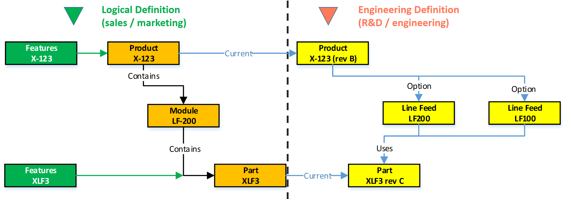
The EBOM
Related to the product or component in the logical definition, there is an actual EBOM, which represents the technical specification of the product. The image above shows the relation represented by the blue “current” link.
 Note: not all systems will support such a data model, and often the marketing sides in managed disconnected from the engineering side. Either in Excel or in a specialized Product Line Engineering (PLE) tools.
We discussed in the previous post that if you want to minimize maintenance, meaning fewer revisions on your EBOM, you should not embed manufacturer-specific parts in your EBOM.
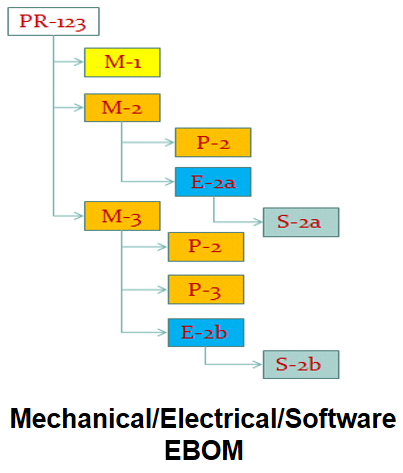 The EBOM typically contains purchase parts and make parts. The purchased parts are sourced based on their specification, and you might have a single source in the beginning. The make parts are entirely under your engineering control, and you define where they are produced and by whom. For the rest, the EBOM might have functional groupings of modules and subassemblies that are defined for reuse by engineering.
Note: An EBOM is the place where multidisciplinary collaboration comes together. This post mainly deals with the mechanical part (as we are looking at the past)
Note: An EBOM can contain multiple valid configurations which you can filter based on a customer or market-specific demand. In this case, we talk about a Configured EBOM or a 150 % EBOM.
The MBOM
 The MBOM represents the way the unique product is going to be manufactured. This means the MBOM-structure will represent the manufacturing steps. For each EBOM-purchase-part, the approved manufacturer for that plant needs to be selected. For each make-part in the EBOM, if made in this plant per customer order, the EBOM parts need to be resolved by one or more manufacturing steps combined with purchased materials.
Let us look at some examples:
The flat MBOM
Some companies do not have real machinery anymore in their plants, the product they deliver to the market is only assembled at the best financial location. This means that all MBOM-parts should arrive at the shop floor to be assembled there. As an example, we have plant A below.
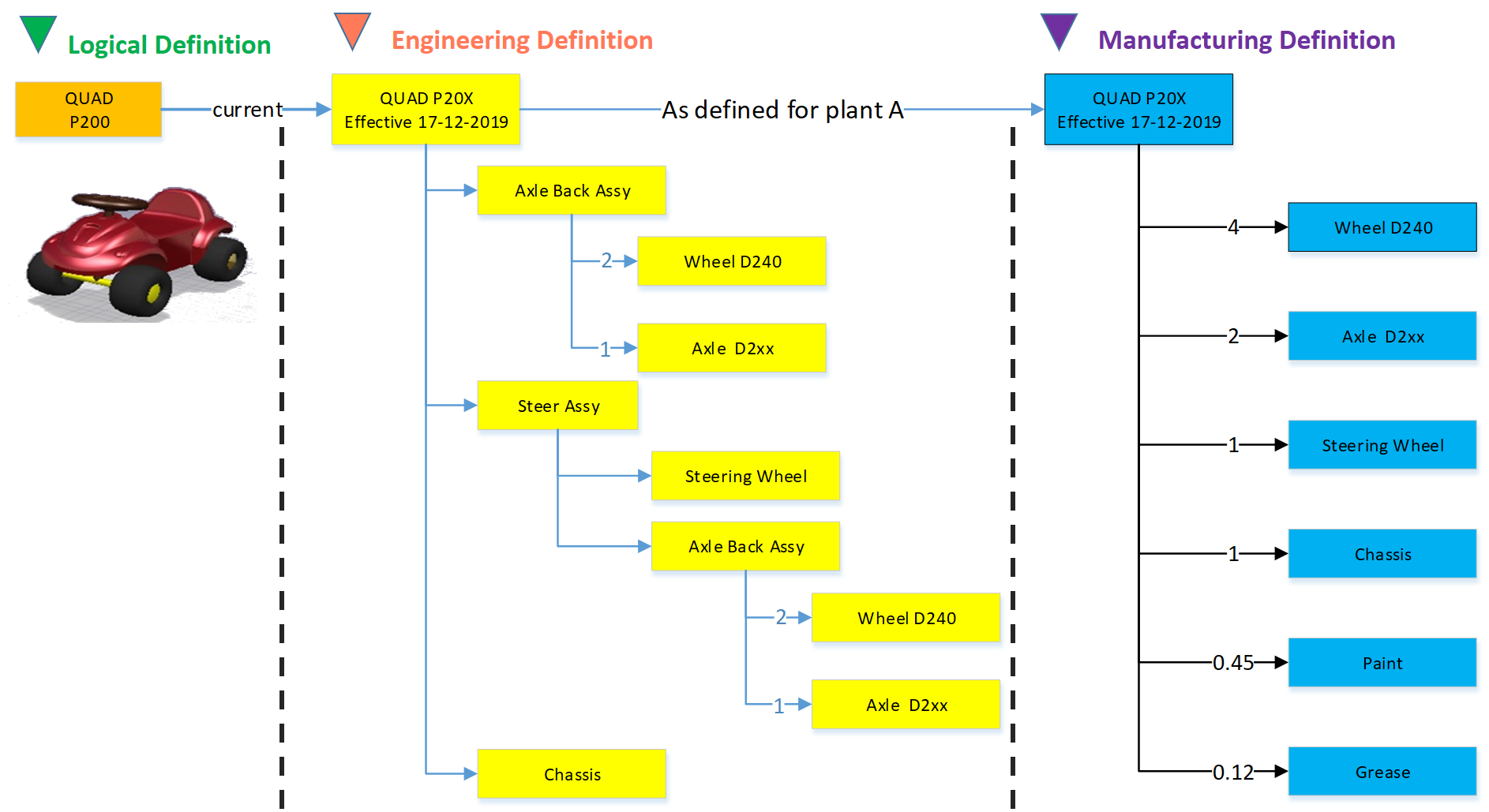
Of course, this is a simplified version to illustrate the basics of the MBOM. The flat MBOM only makes sense if the product is straightforward to assemble. Based on the engineering specifications, the assembly drawing(s) people on the shop floor will know what to do.
The engineering definition specifies that the chassis needs to be painted, and fitting the axles requires grease. These quantities are not visible in the EBOM; they will appear in the MBOM. The quantities and the unit of measure are, of course, relevant here.
Note: The exact quantities for paint and grease might be adjusted in the MBOM when a series of Squads have been manufactured.
The MBOM and Bill of Process
Most of the time, a product is manufactured in several process steps. For that reason, the MBOM is closely related to the Bill of Process or the Routing definitions. The image below illustrates the relationship between an MBOM and the operations in a plant.
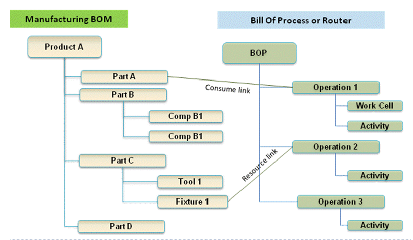
If we continue with our example of the Squad, let us now assume that the wheels and the axle are joined together in a work cell. In addition, the chassis is painted in a separate cell. The MBOM would look like the image below:

In the image, we see that the same Engineering definition now results in a different MBOM. A company can change the MBOM when optimizing the production, without affecting the engineering definition. In this MBOM, the Axle assembly might also be used in other squads manufactured by the company.
The MBOM and purchased parts
 In the previous example, all components for the Squad were manufactured by the same company with the option to produce in Plant A or in Plant B. Now imagine the company also has a plant C in a location where they cannot produce the wheels and axle assembly. Therefore plant C has to “purchase” the Wheel-Axle assembly, and lucky for them plant B is selling the Wheel+Axle assembly to the market as a product.
The MBOM for plant C would look like the image below:
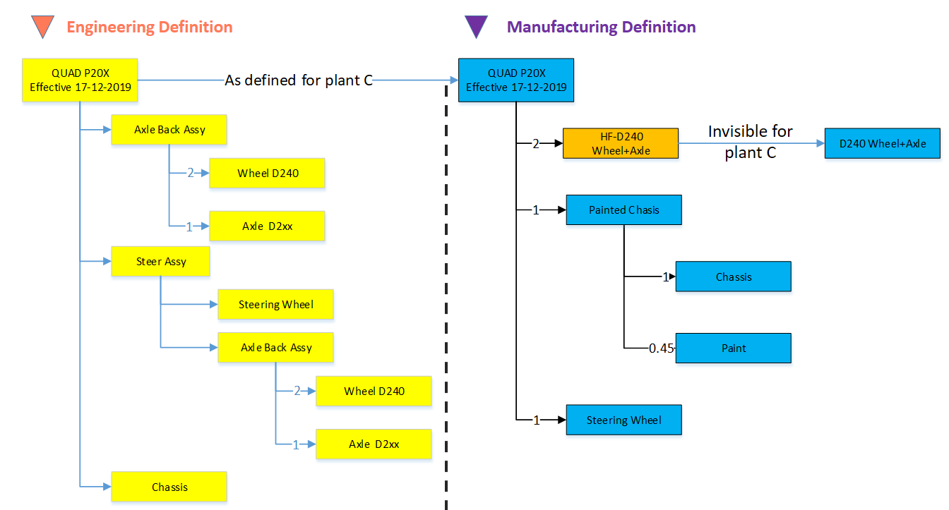
For Plant C, they will order the right amount of the Wheel+Axle product, according to its specifications (HF-D240). How the Wheel+Axle product is manufactured is invisible for Plant C, the only point to check is if the Wheel+Axle product complies with the Engineering Definition and if its purchase price is within the target price range.
Why this simple EBOM-MBOM story?
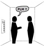 For those always that have been active in the engineering domain, a better understanding of the information flow downstream to manufacturing is crucial. Historically this flow of information has been linear – and in many companies, it is still the fact. The main reason for that lies in the fact that engineering had their own system (PDM or PLM), and manufacturing has their own system (ERP).
Engineers did their best to provide the best engineering specification and release the data to ERP. In the early days, as discussed in Part 4, the engineering specification was most of the time based on a kind of hybrid BOM containing engineering and manufacturing parts already defined.
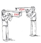 Next, manufacturing engineering uses the engineering specifications to define the manufacturing BOM in the ERP system. Based on the drawings and parts list, they create a preferred manufacturing process (MBOM and BOP) – most of the time, a manual process. Despite the effort done by engineering, there might be a need to change the product. A different shape or dimension make manufacturing more efficient or done with existing tooling. This means an iteration, which causes delays and higher engineering costs.
The first optimization invented was the PDM-ERP interface to reduce the manual work and introduction of typos/misunderstanding of data. This topic was “hot” between 2000 and 2010, and I visited many SmarTeam customers and implementers to learn and later explain that this is a mission impossible. The picture below says it all.
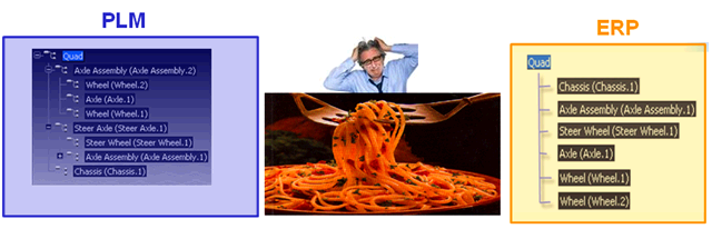
We have an engineering BOM (with related drawings). Through an interface, this EBOM will be restructured into a manufacturing BOM, thanks to all kinds of “clever” programming based on particular attributes. Discussed in Part 3
 The result, however, was that the interface was never covering all situations and became the most expensive part of the implementation.
Good business for the implementing companies, bad for the perception of PDM/PLM.
The lesson learned from all these situations: If you have a PLM-system that can support both the EBOM and MBOM in the same environment, you do not need this complex interface anymore. You can still use some automation to move from an EBOM to an MBOM.
However, three essential benefits come from this approach
- Working in a single environment allows manufacturing engineers to work directly in the context of the EBOM, proposing changes to engineering in the same environment and perform manual restructuring on the MBOM as programming logic does not exist. Still, compare tools will ensure all EBOM-parts are resolved in the manufacturing definition.
- All product Intellectual Property is now managed in a single environment. There is no scattered product information residing in local ERP-systems. When companies moved towards multiple plants for manufacturing, there was the need for a centralized generic MBOM to be resolved for the local plant (local suppliers / local plant conditions). Having the generic MBOM and Bill of Process in PLM was the solution.
- When engineers and manufacturing engineers work in the same environment, manufacturing engineering can start earlier with the manufacturing process definition, providing early feedback to engineering even when the engineering specification has not been released. This approach allows real concurrent engineering, reducing time to market and cost significantly
Conclusion
Again 1600 words this time. We are now at the stage that connecting the EBOM and the MBOM in PLM has become a best practice in most standard PLM-systems. If implemented correctly, the interface to ERP is no longer on the critical path – the technology never has been the limitation – it is all about methodology.
Next time a little bit more on advanced EBOM/MBOM interactions
 Due to some physical inconvenience the upcoming weeks, I will not be able to write a full blog post at this time. Typing with one finger is not productive.
A video post could be an alternative, however for me, the disadvantage of a video message is that it requires the audience to follow all the information in a fixed speed – no fast or selective reading possible – hard to archive and store in context of other information. Putting pieces of information in a relevant context is a PLM-mission.
So this time my post from December 2008, where I predicted the future for 2050. I think the predictions were not too bad – you will recognize some trends and challenges still ahead. Some newer comments in italic green. I am curious to learn what you think after reading this post. Enjoy, and I am looking forward to your feedback
PLM in 2050
 As the year ends (December 2008), I decided to take my crystal ball to see what would happen with PLM in the future.
It felt like a virtual experience and this is what I saw:
- Data is not replicated any more – every piece of information that exists will have a Unique Universal ID; some people might call it the UUID. In 2020 this initiative became mature, thanks to the merger of some big PLM and ERP vendors, who brought this initiative to reality. This initiative reduced the exchange costs in supply chains dramatically and lead to bankruptcy for many companies providing translators and exchange software. (still the dream of a digital enterprise)
- Companies store their data in ‘the cloud’ based on the previous concept. Only some old-fashioned companies still have their own data storage and exchange issues, as they are afraid someone will touch their data. Analysts compare this behavior with the situation in the year 1950, when people kept their money under a mattress, not trusting banks (and they were not always wrong) (we are getting there – sill some years to go)
- After 3D, an entire virtual world, based on holography, became the next step for product development and understanding of products. Thanks to the revolutionary quantum-3D technology, this concept could be even applied to life sciences. Before ordering a product, customers could first experience and describe their needs in a virtual environment (to be replaced by virtual twin / VR / AR)
- Finally the cumbersome keyboard and mouse were replaced by voice and eye-recognition.
Initially voice recognition (Siri, Alexia please come to the PLM domain)
http://www.youtube.com/watch?v=2Y_Jp6PxsSQand eye tracking (some time to go still)were cumbersome. Information was captured by talking to the system and capturing eye-movement when analyzing holograms. This made the life of engineers so much easier, as while analyzing and talking, their knowledge was stored and tagged for reuse. No need for designers to send old-fashioned emails or type their design decisions for future reuse (now moving towards AI)
- Due to the hologram technology, the world became greener. People did not need to travel around the world, and the standard became virtual meetings with global teams(airlines discontinued business class). Even holidays could be experienced in the virtual world thanks to a Dutch initiative based on the experience with coffee. (not sure why I selected this movie. Sorry ….)
http://www.youtube.com/watch?v=HUqWaOi8lYQThe whole IT infrastructure was powered by efficient solar energy, reducing the amount of carbon dioxide dramatically - Then with a shock, I noticed PLM did not longer exist. Companies were focusing on their core business processes. Systems/terms like PLM, ERP, and CRM did not longer exist. Some older people still remembered the battle between these systems to own the data and the political discomfort this gave inside companies (so true …)
- As people were working so efficient, there was no need to work all week. There were community time slots, when everyone was active, but 50 percent of the time, people had the time to recreate (to re-create or recreate was the question). Some older French and German designers remembered the days when they had only 10 weeks holiday per year, unimaginable nowadays. (the dream remains)
As we still have more than 40 years to reach this future, I wish you all a successful and excellent 2009.
I am looking forward to be part of the green future next year.
In my series describing the best practices related to a (PLM) data model, I described the general principles, the need for products and parts, the relation between CAD documents and the EBOM, the topic of classification and now the sensitive relation between EBOM and MBOM.
First some statements to set the scene:
- The EBOM represents the engineering (design) view of a product, structured in a way that it represents the multidisciplinary view of the functional definition of the product. The EBOM combined with its related specification documents, models, drawings, annotations should give a 100 % clear definition of the product.
- The MBOM represents the manufacturing view of a product, structured in a way that represents the way the product is manufactured. This structure is most of the time not the same as the EBOM, due to the manufacturing process and purchasing of parts.

A (very) simplified picture illustrating the difference between an EBOM and a MBOM. If the Car was a diesel there would be also embedded software in both BOMs (currently hidden)
For many years, the ERP systems have claimed ownership of the MBOM for two reasons
- Historically the MBOM was the starting point for production. Where the engineering department often worked with a set of tools, the ERP system was the system where data was connected and used to have a manufacturing plan and real-time execution

- To accommodate a more advanced integration with PDM systems, ERP vendors began to offer an EBOM capability also in their system as PDM systems often worked around the EBOM.

These two approaches made it hard to implement “real” PLM where (BOM) data is flowing through an organization instead of stored in a single system.
By claiming ownership of the BOM by ERP, some problems came up:
- A disconnect between the iterative engineering domain and the execution driven ERP domain. The EBOM is under continuous change (unless you have a simple or the ultimate product) and these changes are all related to upstream information, specifications, requirements, engineering changes and design changes. An ERP system is not intended for handling iterative processes, therefore forcing the user to work in a complex environment or trying to fix the issue through heavy customization on the ERP side.

- Global manufacturing and outsourced manufacturing introduced a new challenge for ERP-centric implementations. This would require all manufacturing sites also the outsourced manufacturers the same capabilities to transfer an EBOM into a local MBOM. And how do you capitalize the IP from your products when information is handled in a dispersed environment?


The solution to this problem is to extend your PDM implementation towards a “real” PLM implementation providing the support for EBOM, MBOM, and potential plant specific MBOM. All in a single system / user-experience designed to manage change and to allow all users to work in a global collaborative way around the product. MBOM information then will then be pushed when needed to the (local) ERP system, managing the execution.

Note 1: Pushing the MBOM to ERP does not mean a one-time big bang. When manufacturing parts are defined and sourced, there will already be a part definition in the ERP system too, as logistical information must come from ERP. The final push to ERP is, therefore, more a release to ERP combined with execution information (when / related to which order).
In this scenario, the MBOM will be already in ERP containing engineering data complemented with manufacturing data. Therefore from the PLM side we talk more about sharing BOM information instead of owning. Certain disciplines have the responsibility for particular properties of the BOM, but no single ownership.
Note 2: The whole concept of EBOM and MBOM makes only sense if you have to deliver repetitive products. For a one-off product, more a project, the engineering process will have the manufacturing already in mind. No need for a transition between EBOM and MBOM, it would only slow down the delivery.
Now let´s look at some EBOM-MBOM specifics
EBOM phantom assemblies
 When extracting an EBOM directly from a 3D CAD structure, there might be subassemblies in the EBOM due to a logical grouping of certain items. You do not want to see these phantom assemblies in the MBOM as they only complicate the structuring of the MBOM or lead to phantom activities. In an EBOM-MBOM transition these phantom assemblies should disappear and the underlying end items should be linked to the higher level.
EBOM materials
In the EBOM, there might be materials like a rubber tube with a certain length, a strip with a certain length, etc. These materials cannot be purchased in these exact dimensions. Part of the EBOM to MBOM transition is to translate these EBOM items (specifying the exact material) into purchasable MBOM items combined with a fitting operation.
EBOM end-items (make)
For make end-items, there are usually approved manufacturers defined and it is desirable to have multiple manufacturers (certified through the AML) for make end-items, depending on cost, capacity and where the product needs to be manufactured. Therefore, a make end-item in the EBOM will not appear in a resolved MBOM.
EBOM end-items (buy)
For buy end-items, there is usually a combination of approved manufacturers (AML) combined with approved vendors (AVL). The approved manufacturers are defined by engineering, based on part specifications. Approved vendors are defined by manufacturing combined with purchasing based on the approved manufacturers and logistical or commercial conditions
Are EBOM items and MBOM items different?
 There is a debate if EBOM items should/could appear in an MBOM or that EBOM items are only in the EBOM and connected to resolved items in the MBOM. Based on the previous descriptions of the various EBOM items, you can conclude that a resolved MBOM does not contain EBOM items anymore in case of multiple sourcing. Only when you have a single manufacturer for an EBOM item, the EBOM item could appear in the MBOM. Perhaps this is current in your company, but will this stay the same in the future?
It is up to your business process and type of product which direction you choose. Coming back to one-off products, here is does not make sense to have multiple manufacturers. In that case, you will see that the EBOM item behaves at the same time as an MBOM item.
What about part numbering?
 Luckily I reached the 1000 words so let´s be short on this debate. In case you want an automated flow of information between PLM and ERP, it is important that shared data is connected through a unique identifier.
Automation does no need intelligent numbering. Therefore giving parts in the PLM system and the ERP system a unique, meaningless number you ensure guaranteed digital connectivity.
If you want to have additional attributes on the PLM or ERP side that describe the part with a number relevant for human identification on the engineering side or later at the manufacturing side (labeling), this all can be solved.
An interesting result of this approach is that a revision of a part is no longer visible on the ERP side (unless you insist). Each version of the MBOM parts is pointing to a unique version of an MBOM part in ERP, providing an error free sharing of data.
Conclusion
Life can be simple if you generalize and if there was no past, no legacy and no ownership of data thinking. The transition of EBOM to MBOM is the crucial point where the real PLM vision is applied. If there is no data sharing on MBOM level, there are two silos, the characteristic of the old linear past.
(See also: From a linear world to a circular and fast)
What do you think? Is more complexity needed?

I will be soon discussing these topics at the PDT2015 in Stockholm on October 13-14. Will you be there ?
And for Dutch/Belgium readers – October 8th in Bunnik:

Op 8 oktober ben ik op het BIM Open 2015 Congres in Bunnik waar ik de overeenkomsten tussen PLM en BIM zal bespreken en wat de constructie industrie kan leren van PLM

Hi Jos, Knowing your background in methodology and education, I wanted to share a longer article with you: “What is…
Interesting reflection, Jos. In my experience, the situation you describe is very recognizable. At the company where I work, sustainability…
[…] (The following post from PLM Green Global Alliance cofounder Jos Voskuil first appeared in his European PLM-focused blog HERE.) […]
[…] recent discussions in the PLM ecosystem, including PSC Transition Technologies (EcoPLM), CIMPA PLM services (LCA), and the Design for…
Jos, all interesting and relevant. There are additional elements to be mentioned and Ontologies seem to be one of the…