
 In March 2018, I started a series of blog posts related to model-based approaches. The first post was: Model-Based – an introduction. The reactions to these series of posts can be summarized in two bullets:
- Readers believed that the term model-based was focusing on the 3D CAD model. A logical association as PLM is often associated with 3D CAD-model data management (actually PDM), and in many companies, the 3D CAD model is (yet) not a major information carrier/
- Readers were telling me that a model-based approach is too far from their day-to-day life. I have to agree here. I was active in some advanced projects where the product’s behavior depends on a combination of hardware and software. However, most companies still work in a document-driven, siloed discipline manner merging all deliverables in a BOM.
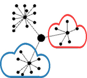 More than 3 years later, I feel that model-based approaches have become more and more visible for companies. One of the primary reasons is that companies start to collaborate in the cloud and realize the differences between a coordinated and a connected manner.
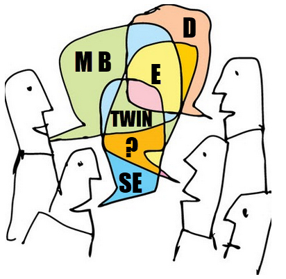
Initiatives as Industry 4.0 or concepts like the Digital Twin demand a model-based approach. This post is a follow-up to my recent post, The Future of PLM.
History has shown that it is difficult for companies to change engineering concepts. So let’s first look back at how concepts slowly changed.
The age of paper drawings
 In the sixties of the previous century, the drawing board was the primary “tool” to specify a mechanical product. The drawing on its own was often a masterpiece drawn on special paper, with perspectives, details, cross-sections.
All these details were needed to transfer the part or assembly information to manufacturing. The drawing set should contain all information as there were no computers.
 Making a prototype was, depending on the complexity of the product, the interpretation of the drawings and manufacturability of a product, not always that easy. After a first release, further modifications to the product definition were often marked on the manufacturing drawings using a red pencil. Terms like blueprint and redlining come from the age of paper drawings.
There are still people talking nostalgically about these days as creating and interpreting drawings was an important skill. However, the inefficiencies with this approach were significant.
- First, updating drawings because there was redlining in manufacturing was often not done – too much work.
- Second, drawing reuse was almost impossible; you had to start from scratch.
- Third, and most importantly, you needed to be very skilled in interpreting a drawing set. In particular, when dealing with suppliers that might not have the same skillset and the knowledge of which drawing version was actual.
 However, paper was and still is the cheapest neutral format to distribute designs. The last time I saw companies still working with paper drawings was at the end of the previous century.
Curious to learn if they are now extinct?
The age of electronic drawings (CAD)
With the introduction of AutoCAD and personal computers around 1982, more companies started to look into drafting with the computer. There was already the IBM drafting system in 1965, but it was Autodesk that pushed the 2D drafting business with their slogan:
“80 percent of the functionality for 20 percent of the price (Autodesk 1982)”
A little later, I started to work for an Autodesk distributor/reseller. People would come to the showroom to see how a computer drawing could be plotted in the finest quality at the end. But, of course, the original draftsman did not like the computer as the screen was too small.
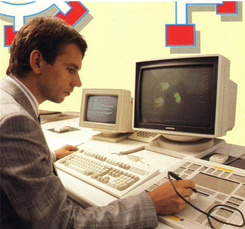 However, the enormous value came from making changes, the easy way of sharing drawings and the ease of reuse. The picture on the left is me in 1989, demonstrating AutoCAD with a custom-defined tablet and PS/2 computer.
The introduction of electronic drawings was not a disruption, more optimization of the previous ways of working.
The exchange with suppliers and manufacturing could still be based on plotted drawings – the most neutral format. And thanks to the filename, there was better control of versions between all stakeholders.
Aren’t we all happy?
The introduction of mainstream 3D CAD
 In 1995, 3D CAD became available for the mid-market, thanks to SolidWorks, Solid Edge and a little later Inventor. Before that working with 3D CAD was only possible for companies that could afford expensive graphic stations, provided by IBM, Silicon Graphics, DEC and SUN. Where are they nowadays? The PC is an example of disruptive innovation, purely based on technology. See Clayton Christensen’s famous book: The Innovator’s Dilemma.
The introduction of 3D CAD on PCs in the mid-market did not lead directly to new ways of working. Designing a product in 3D was much more efficient if you mastered the skills. 3D brought a better understanding of the product dimensions and shape, reducing the number of interpretation errors.
 Still, (electronic) drawings were the contractual deliverable when interacting with suppliers and manufacturing. As students were more and more trained with the 3D CAD tools, the traditional art of the draftsman disappeared.
3D CAD introduced some new topics to solve.
- First of all, a 3D CAD Assembly in the system was a collection of separate files, subassemblies, parts, and drawings that relate to each other with a specific version. So how to ensure the final assembly drawings were based on the correct part revisions? Companies were solving this by either using intelligent filenames (with revisions) or by using a PDM system where the database of the PDM system managed all the relations and their status.
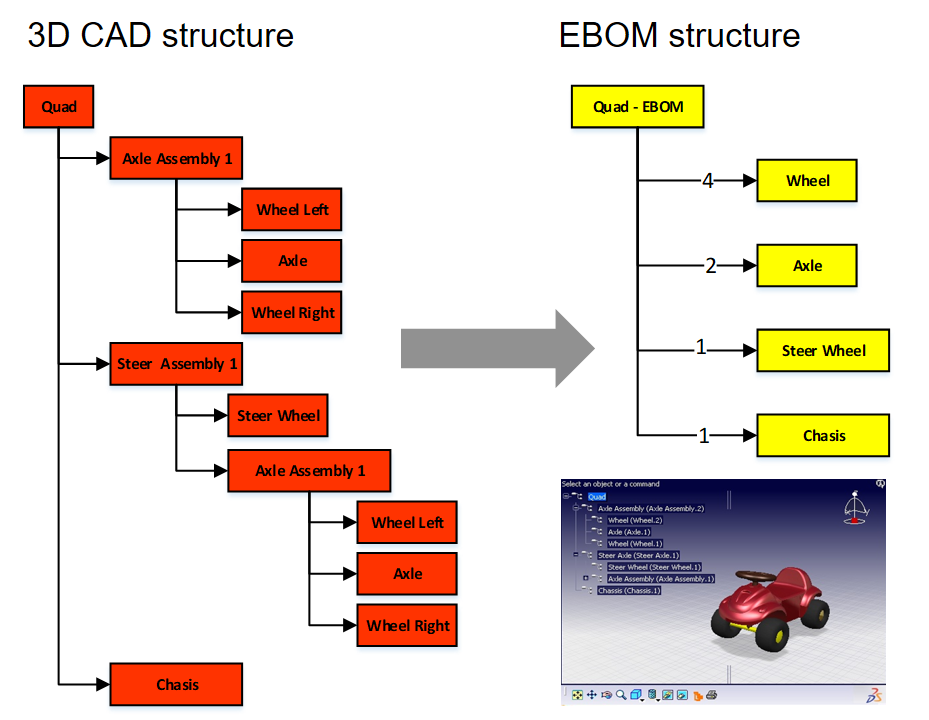
- The second point was that the 3D CAD assembly also introduced a new feature, the product structure, or the “Bill of Materials”. This logical structure of the assembly up resembled a lot of the Bill of Material of the product. You could even browse deeper levels, which was not the case in the traditional Bill of Material on a drawing.
Note: The concept of EBOM and MBOM was not known in most companies. People were talking about the BOM as a one-level definition of parts or subassemblies in the assembly. See my Where is the MBOM? Post from July 2008 when this topic was still under discussion.
- The third point that would have a more significant impact later is that parts and assemblies could be reused in other products. This introduced the complexity of configuration management. For example, a 3D CAD part or assembly file could contain several configurations where only one configuration would be valid for the given product. Managing this in the 3D CAD system lead to higher productivity of the designer, however downstream when it came to data management with PDM systems, it became a nightmare.

I experienced these issues a lot when discussing with companies and implementers, mainly the implementation of SmarTeam combined with SolidWorks and Inventor. Where to manage the configuration constraints? In the PDM system or inside the 3D CAD system.
These environments were not friends (image above), and even if they came from the same vendor, it felt like discussing with tribes.
The third point also covered another topic. So far, CAD had been the first step for the detailed design of a product. However, companies now had an existing Bill of Material in the system thanks to the PDM systems. It could be a Bill of Material of a sub-assembly that is used in many other products.
Configuring a product no longer started from CAD; it started from a Product or Bill of Material structure. Sales and Engineers identified the changes needed on the BoM, keeping as much as possible released information untouched. This led to a new best practice.
The item-centric approach
 Around 2005, five years after introducing the term Product Lifecycle Management, slowly, a new approach became the standard. Product Lifecycle Management was initially introduced to connect engineering and manufacturing, driven by the automotive and aerospace industry.
It was with PLM that concepts as EBOM and MBOM became visible.
In particular, the EBOM was closely linked to engineering practices, i.e., modularity and reuse. The EBOM and its related information represented the product as it was specified. It is essential to realize that the parts in the EBOM could be generic specified purchase parts to be resolved when producing the product or that the EBOM contained Make-parts specified by drawings.
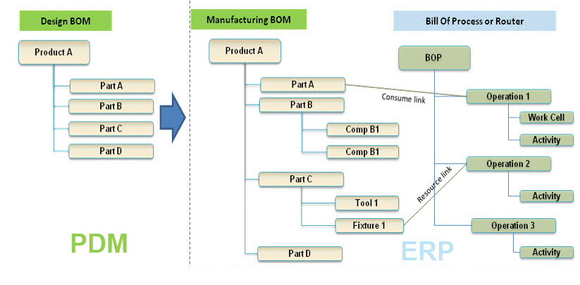
At that time, the EBOM was often used as the foundation for the ERP system – see image above. The BOM was restructured and organized according to the manufacturing process specifying materials and resources needed in the ERP system. Therefore, although it was an item-like structure, this BOM (the MBOM) always had a close relation to the Bill of Process.
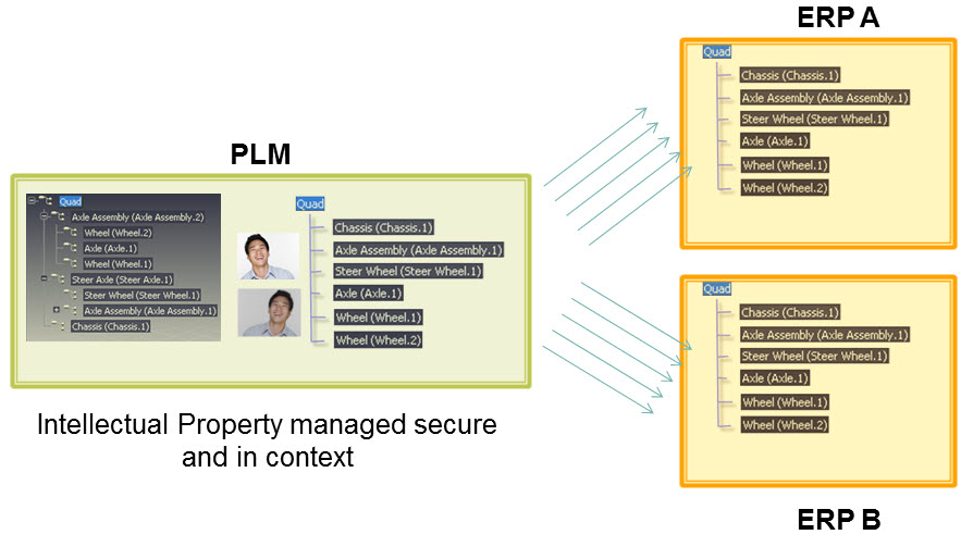
For companies with a single manufacturing site, the notion of EBOM and MBOM was not that big, as the ERP system would be the source of the MBOM. However, the complexity came when companies have several manufacturing sites. That was when a generic MBOM in the PLM system made more sense to centralize all product information in a single system.
The EBOM-MBOM approach has become more and more a standard practice since 2010. As a result, even small and medium-sized enterprises realized a need to manage the EBOM and the MBOM.
There were two disadvantages introduced with this EBOM-MBOM approach.
- First, the EBOM and the MBOM as information structures require a lot of administrative maintenance if information needs to be always correct (and that is the CM target). Some try to simplify this by keeping the EBOM part the same as the MBOM part, meaning the EBOM specification already targets a single supplier or manufacturer.
- The second disadvantage of making every item in the BOM behave like a part creates inefficiencies in modern environments. Products are a mix of hardware(parts) and software(models/behavior). This BOM-centric view does not provide the proper infrastructure for a data-driven approach as part specifications are still done in drawings. We need 3D annotated models related to all kinds of other behavior and physical models to specify a product that contains hard-and software.
 A new paradigm is needed to manage this mix efficiently, the enabling foundation for Industry 4.0 and efficient Digital Twins; there is a need for a model-based approach based on connected data elements.
More next week.
Conclusion
| The age of paper drawings | 1960 – now dead |
| The age of electronic drawings | 1982 – potentially dead in 2030 |
| The mainstream 3D CAD | 1995 – to be evolving through MBD and MBSE to the future – not dead shortly |
| Item-centric approach | 2005 – to be evolving to a connected model-based approach – not dead shortly |
Discover more from Jos Voskuil's Weblog
Subscribe to get the latest posts sent to your email.

Leave a comment
Comments feed for this article