
You are currently browsing the category archive for the ‘3D CAD management’ category.
 Two weeks ago, I shared my first post about PDM/PLM migration challenges on LinkedIn: How to avoid Migration Migraine – part 1. Most of the content discussed was about data migrations.
Starting from moving data stored in relational databases to modern object-oriented environments – the technology upgrade. But also the challenges a company can have when merging different data siloes (CAD & BOM related) into a single PLM backbone to extend the support of product data beyond engineering.
 Luckily, the post generated a lot of reactions and feedback through LinkedIn and personal interactions last week.
The amount of interaction illustrated the relevance of the topic for people; they recognized the elephant in the room, too.
Working with a partner
 Data migrations and consolidation are typically not part of a company’s core business, so it is crucial to find the right partner for a migration project. The challenge with migrations is that there is potentially a lot to do technically, but only your staff can assess the quality and value of migrations.
Therefore, when planning a migration, make sure you work on it iteratively with an experienced partner who can provide a set of tools and best practices. Often, vendors or service partners have migration tools that still need to be tuned to your As-Is and To-Be environment.
 To get an impression of what a PLM service partner can do and which topics or tools are relevant in the context of mid-market PLM, you can watch this xLM webinar on YouTube. So make sure you select a partner who is familiar with your PDM/PLM infrastructure and who has the experience to assess complexity.
Migration lessons learned
 In my PLM coaching career I have seen many migrations. In the early days they were more related to technology upgrades, consolidation of data and system replacements. Nowadays the challenges are more related to become more data-driven. Here are 5 lessons that I learned in the past twenty years:
- A fixed price for the migration can be a significant risk as the quality of the data and the result are hard to comprehend upfront. In case of a fixed price, either you would pay for the moon (taking all the risk), or your service partner would lose a lot of money. In a sustainable business model, there should be no losers.
- Start (even now) with checking and fixing your data quality. For example, when you are aware of a mismatch between CAD assemblies and BOM data, analyze and fix discrepancies even before the migration.
- One immediate action to take when moving from CAD assemblies to BOM structures is to check or fill the properties in the CAD system to support a smooth transition. Filling properties might be a temporary action, as later, when becoming more data-driven, some of these properties, e.g., material properties or manufacturer part numbers, should not be maintained in the CAD system anymore. However, they might help migration tools to extract a richer dataset.
- Focus on implementing an environment ready for the future. Don’t let your past data quality compromise complexity. In such a case, learn to live with legacy issues that will be fixed only when needed. A 100 % matching migration is not likely to happen because the source data might also be incorrect, even after further analysis.
- The product should probably not be configured in the CAD environment, even because the CAD tool allows it. I had this experience with SolidWorks in the past. PDM became the enemy because the users managed all configuration options in the assembly files, making it hard to use it on the BOM or Product level (the connected digital thread).
The future is data-driven
 In addition, these migration discussions made me aware again that so many companies are still in the early phases of creating a unified PLM infrastructure in their company and implementing the coordinated approach – an observation I shared in my report on the PDSFORUM 2024 conference.
Due to sustainability-related regulations and the need to understand product behavior in the field (Digital Twin / Product As A Service), becoming data-driven is an unavoidable target in the near future. Implementing a connected digital thread is crucial to remaining competitive and sustainable in business.
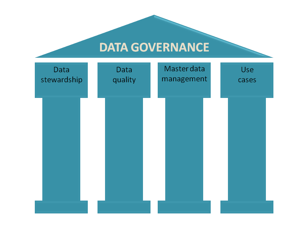 However, the first step is to gain insights about the available data (formats and systems) and its quality. Therefore, implementing a coordinated PLM backbone should immediately contain activities to improve data quality and implement a data governance policy to avoid upcoming migration issues.
Data-driven environments, the Systems of Engagement, bring the most value when connected through a digital thread with the Systems of Record (PLM. ERP and others), therefore, design your processes, even current ones, user-centric, data-centric and build for change (see Yousef Hooshmand‘s story in this post – also image below).

The data-driven Future is not a migration.
The last part of this article will focus on what I believe is a future PLM architecture for companies. To be more precise, it is not only a PLM architecture anymore. It should become a business architecture based on connected platforms (the systems of record) and inter-platform connected value streams (the systems of engagement).
 The discussion is ongoing, and from the technical and business side, I recommend reading Prof Dr. Jorg Fischer’s recent articles, for example. The Crisis of Digitalization – Why We All Must Change Our Mindset! or The MBOM is the Steering Wheel of the Digital Supply Chain! A lot of academic work has been done in the context of TeamCenter and SAP.
 Also, Martin Eigner recently described in The Constant Conflict Between PLM and ERP a potential digital future of enterprise within the constraints of existing legacy systems.
In my terminology, they are describing a hybrid enterprise dominated by major Systems of Record complemented by Systems of Engagement to support optimized digital value streams.
 Whereas Oleg Shilovitsky, coming from the System of Engagement side with OpenBOM, describes the potential technologies to build a digital enterprise as you can read from one of his recent posts: How to Unlock the Future of Manufacturing by Opening PLM/ERP to Connect Processes and Optimize Decision Support.
All three thought leaders talk about the potential of connected aspects in a future enterprise. For those interested in the details there is a lot to learn and understand.
For the sake of the migration story I stay out of the details. However interesting to mention, they also do not mention data migration—is it the elephant in the room?
 I believe moving from a coordinated enterprise to a integrated (coordinated and connected) enterprise is not a migration, as we are no longer talking about a single system that serves the whole enterprise.
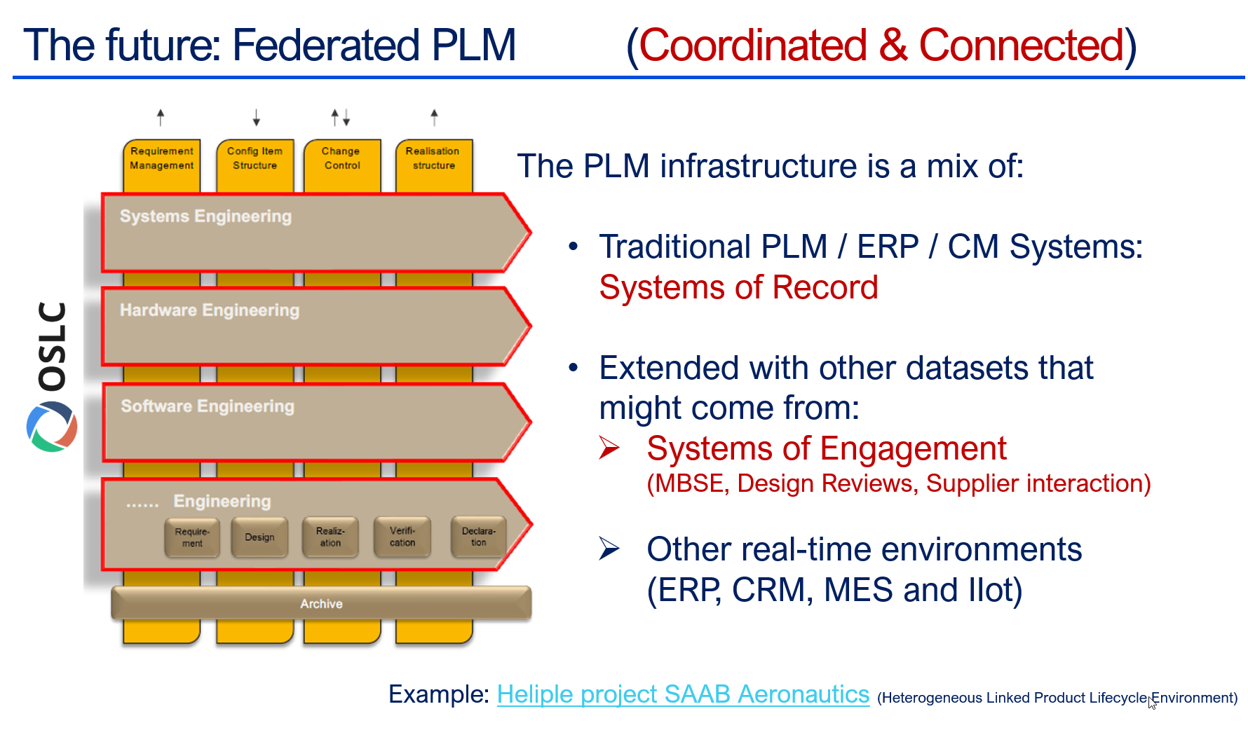
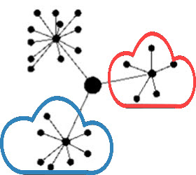
The future of a digital enterprise is a federated environment where existing systems need to become more data-driven, and additional collaboration environments will have their internally connected capabilities to support value streams.
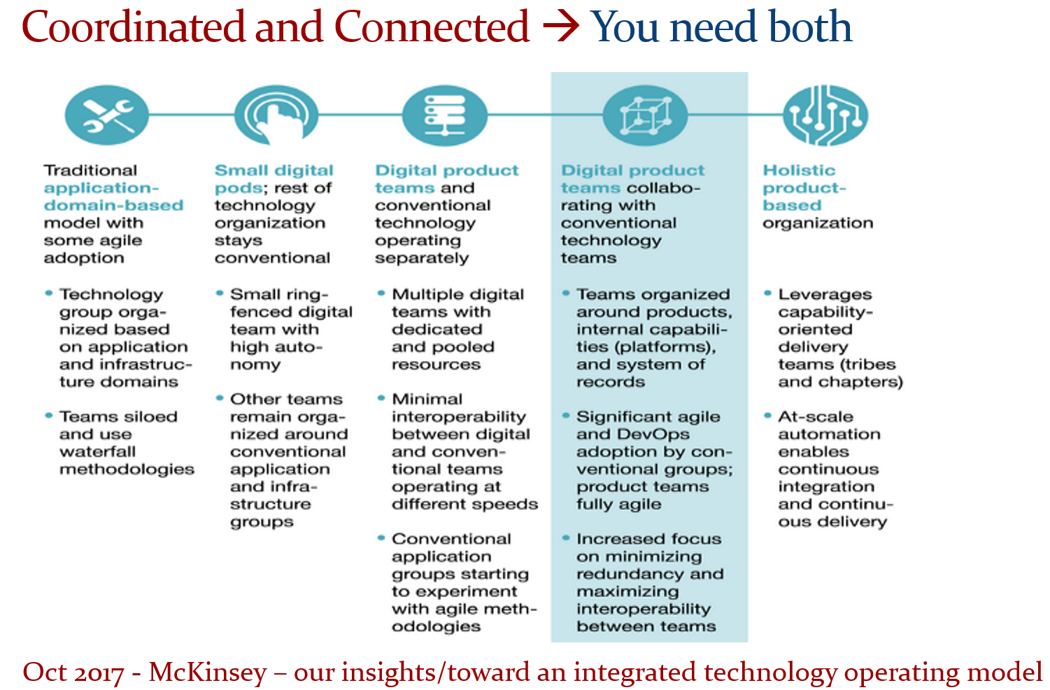
With this in mind you can understand the 2017 McKinsey article– Our insights/toward an integrated technology operating model – the leading image below:
And when it comes to realization of such a concept, I have described the Heliple-2 project a few times before as an example of such an environment, where the target is to have a connection between the two layers through standardized interfaces, starting from OSLC. Or visit the Heliple Federated PLM LinkedIn group.
Data architecture and governance are crucial.
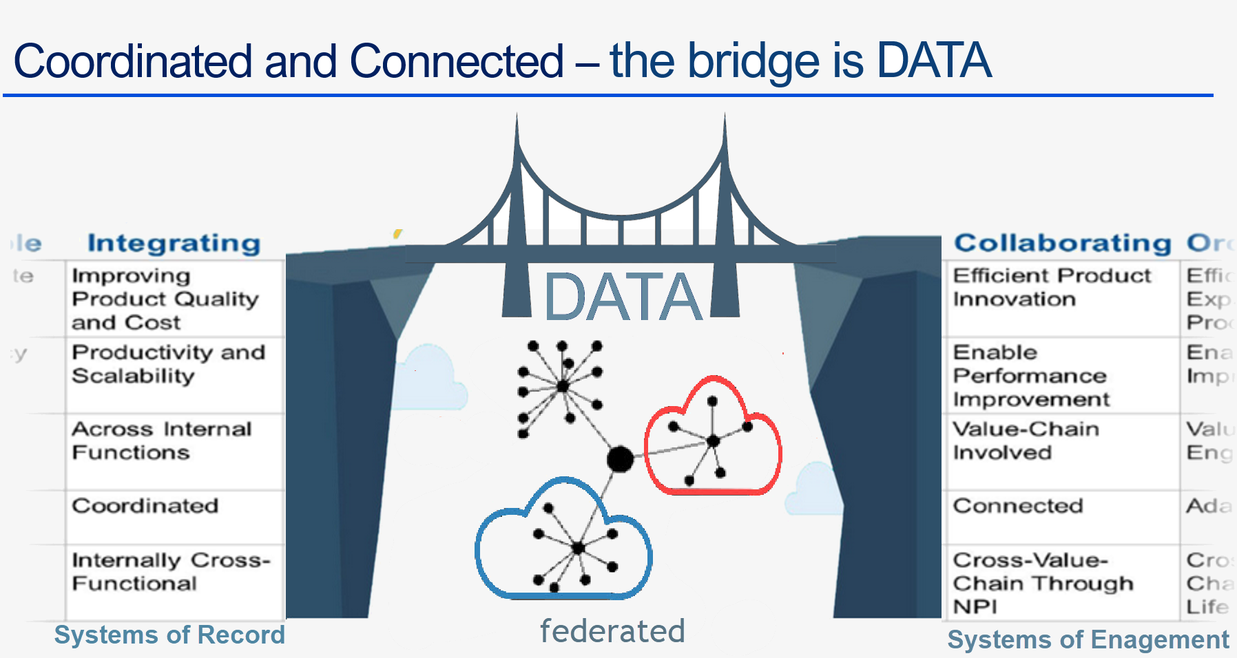
The image above generalizes the federated PLM concept and illustrates the two different systems connected through data bridges. As data must flow between the two sides without human intervention, the chosen architecture must be well-defined.
 Here, I want to use a famous quote from Youssef Housmand’s paper From a Monolithic PLM Landscape to a Federated Domain and Data Mesh. Click on the image to listen to the Share PLM podcast with Yousef.
From a Single Source of Truth towards a principle of the Nearest Source of Truth based on a Single Source of Change
- If you agree with this quote, you have a future mindset of federated PLM.
- If you still advocate the Single Source of Truth, you are still in the Monolithic PLM phase.
It’s not a problem if you are aware that the next step should be federated and you are not ready yet.

However, in particular, environmental regulations and sustainability initiatives can only be performed in data-driven, federated environments. Think about the European Green Deal with its upcoming Ecodesign for Sustainable Products Directive (ESPR), which demands digital traceability of products, their environmental impact, and reuse /recycle options, expressed in the Digital Product Passport.
 Reporting, Greenhouse Gas Reporting and ESG reporting are becoming more and more mandatory for companies, either by regulations or by the customers. Only a data-driven connected infrastructure can deal with this efficiently. Sustaira, a company we interviewed with the PLM Green Global Alliance last year, delivers such a connected infrastructure.
Read the challenges they meet in their blog post: Is inaccurate sustainability data holding you back?
Finally, to perform Life Cycle Assessments for design options or Life Cycle Analyses for operational products, you need connections to data sources in real-time. The virtual design twin or the digital twin in operation does not run on documents.
Conclusion
Data migration and consolidation to modern systems is probably a painful and challenging process. However, the good news is that with the right mindset to continue and with a focus on data quality and governance, the next step to a integrated coordinated and connected enterprise will not be that painful. It can be an evolutionary process, as the McKinsey article describes it.

 In the past months, I have had several discussions related to migrating PLM data, either from one system to another or from consolidating a collection of applications into a single environment. Does this sound familiar?
Let me share some experiences and lessons learned to avoid the Migration Migraine.
It is not a technical guide but a collection of experiences and thoughts that you might have missed when considering to solve the technical dream.
 Halfway I realized I was too ambitious; therefore, another post will follow this introduction. Here, I will focus on the business side and the digital transformation journey.
Garbage Out – Garbage In
 The Garbage Out-In statement is somehow the paradigm we are used to in our day-to-day lives. When you buy a new computer, you use backup and restore. Even easier, nowadays, the majority of the data is already in the cloud.
This simple scenario assumes that all professional systems should be easily upgrade-able. We become unaware of the amount of data we store and its relevance.
This phenomenon already has a name: “Dark Data.” Dark Data consumes storage energy in the cloud and is no longer visible. Please read all about it here: Dark Data.
 TIP 1: Every migration is a moment to clean up your data. By dragging everything with you, the burden of migrating becomes bigger. In easy migrations, do a clean-up—it prevents future, more extensive issues.
Never follow the Garbage Out – Garbage in principle, even if it is easy!
Migrations in the PLM domain are different – setting the scene.
 Before discussing the various scenarios, let’s examine what companies are doing. For early PLM adopters in the Automotive, Aerospace, and Defense Industries, migrations from mainframes to modern infrastructures have become impossible. The real problem is not only the changing hardware but also the changing data and data models.
For these companies, the solution is often to build an entirely new PLM infrastructure on top of the existing infrastructure, where manageable data pieces are migrated to new environments using data lakes, dashboards, and custom apps to support modern users.
Migration in this case is a journey as long as the data lives – and we can learn from them!
Follow the money
 From a business perspective, migrations are considered a negative distractor. Talking about them raises awareness of their complexity, which might jeopardize enthusiasm.
For the initiator, the PLM software vendor or implementer, it might endanger the sales deal.
Traditional IT organizations strive for simplification—one CAD, one PLM or one ERP system to manage. Although this argument makes sense, an analysis should always be done comparing the benefits and the (migration) costs and risks to reach the ideal situation.
In those discussions often, migrations are downplayed

Without naming companies, I have observed the downplaying several times, even at some prominent enterprises. So, if you recognize your company in this process, you are not alone.
TIP 2: Migrations are never simple. Make migration a serious topic of your PLM project – as important as the software. This approach means analyzing the potential migration risks and their mitigation is needed.
Please read about the Xylem story in my recent post: The week after the PDSFORUM 2024
The Big Bang has the highest risk and might again lead to garbage out—garbage in.
You are responsible for your garbage.
It may sound disparaging, but it is not. Most companies are aware that people, tools and policies have changed over the years. Due to the coordinated approach to working, disciplines did not need to care about downstream or upstream usage of their initially created data – Excel and PDFs are the bridges between disciplines.

All the actual knowledge and context are stored in the heads of experienced employees who have gotten used to dealing with inconsistencies. And they will retire, so there is an urgent need for actual data quality and governance. Read more about the journey from Coordinated to Connected in these articles.
Even if you are not yet thinking about migrations, the digital transformation in the PLM domain is coming, and we should learn to work in a connected mode.
TIP 3: Create a team in your organization that assesses the current data quality and defines the potential future enterprise (data) architecture. Then, start improving the quality of the current generated data. Like the ISO 900x standard, the ISO 8000 standard already exists for data quality.
The future is data-driven; prepare yourself for the future.
Migration scenarios and their best practices
Here are some migrations scenario’s – two in this post and more in an upcoming post.
From Relational to Object-oriented
 One of my earlier projects, starting in 2010 with SmarTeam, was migrating a mainframe-based application for airplane certification to a modern Microsoft infrastructure.
The goal was to create a new environment that could be used both as a replacement for the mainframe application and as the design and validation environment to implement changes to the current airplanes during a maintenance or upgrade activity.
The need was high because detailed documentation about the logic of the current application did not exist, and only one person who understood the logic was partly available.
So, internally, the relational database was a black box. The tables in the database contained a mix of item data, document data, change status and versions. The documents were stored in directories with meaningful file names but disconnected from the application.

The initial estimate was that the project would take two to three months, so a fixed price for two months was agreed upon. However, it became almost a two-year project, and in the end, the result seemed to be reliable (there was never mathematical proof).
 The disadvantage was that SmarTeam ended up being so highly customized that automatic upgrades would not work for this version anymore—a new legacy was created with modern technology.
The same story, combined with the example of Ericsson’s migration attempt, is described in the 2016 post, The PLM Migration Dilemma. For me, the lesson learned from these examples leads to the following recommendation.
TIP 4: When there is a paradigm change in the data model, don’t migrate but establish a new (data-driven) infrastructure and connect to your legacy as much as possible in read-only mode.
The automotive and aerospace industries’ story is one of paradigm change.
 Listen to the SharePLM podcast Revolutionizing PLM: Insights from Yousef Hooshmand, where Yousef also discusses how to address this transition process.
CAD/PDM to PLM
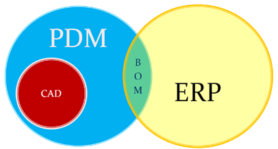 Another migration step happens when companies decide to implement a traditional PLM infrastructure as a System of Record, merging PDM data (mainly CAD) and ERP data (the BOM).
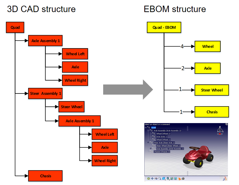
Some of these companies have been working file-based and have stored their final CAD files in folders; others might have a local PDM system native to the 3D CAD. The EBOM usually existed digitally in ERP, and most of the time, it is not a “pure” EBOM but more of a hybrid EBOM/MBOM.

The image above show this type of migration can be very challenging as, in the source systems, there is not necessarily a consistent 3D CAD definition matching the BOM items. As the systems have been disconnected in the past, people have potentially added missing information or fixed information on the BOM side. As in most companies, the manufacturing definition is based on drawings, and the consistency with the 3D CAD definition is not guaranteed.
To address this challenge, companies need to assess the usability of the CAD and BOM data. Is it possible to populate the CAD files with properties that are necessary for an import? For example, does the file path contain helpful information?
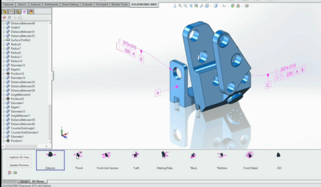
 I have experienced a situation where a company has poorly defined 3D parts and no properties, as all the focus was on using the 3D to generate the 2D drawing.
The relevant details for manufacturing were next added to the drawing and not anymore to the parts or models – traceability was almost impossible.
In this situation, importing the 3D CAD structures into the new PLM system has limited value. An alternative is to describe and test procedures for handling legacy data when it is needed, either to implement a design change or a new order. Leave the legacy accessible, but do not migrate.
The BOM side is, in theory, stable for manufactured products, as the data should have gone through a release process. However, the company needs to revisit its part definition process for new designs and products.
Some points to consider:
- Meaningful identifiers are not desired in a PLM system as they create a legacy. Therefore, the import of parts with smart identifiers should map to relevant part properties besides the ID. Splitting the ID into properties will create a broader usage in the future. Read more in Smart Part Numbers – do we need them?

- In addition, companies should try to avoid having logistic information, such as supplier-specific part numbers to come from the CAD system. Supplier parts in your CAD environment create inefficiencies when a supplier part becomes obsolete. Concepts such as EBOM and MBOM and potentially the SBOM should be well understood during this migration.

- Concepts of EBOM and MBOM should also be introduced when moving from an ETO to a CTO approach or when modularity is a future business strategy.


Conclusion
As every company is on its PLM journey and technology is evolving, there will always be a migration discussion. Understanding and working towards the future should be the most critical driver for migration. Migrations in the PLM domain are often more than a data migration – new ways of working should be introduced in parallel. And for that reason the “big bang” is often too costly and demotivating for the future.
 In March 2018, I started a series of blog posts related to model-based approaches. The first post was: Model-Based – an introduction. The reactions to these series of posts can be summarized in two bullets:
- Readers believed that the term model-based was focusing on the 3D CAD model. A logical association as PLM is often associated with 3D CAD-model data management (actually PDM), and in many companies, the 3D CAD model is (yet) not a major information carrier/
- Readers were telling me that a model-based approach is too far from their day-to-day life. I have to agree here. I was active in some advanced projects where the product’s behavior depends on a combination of hardware and software. However, most companies still work in a document-driven, siloed discipline manner merging all deliverables in a BOM.
 More than 3 years later, I feel that model-based approaches have become more and more visible for companies. One of the primary reasons is that companies start to collaborate in the cloud and realize the differences between a coordinated and a connected manner.
Initiatives as Industry 4.0 or concepts like the Digital Twin demand a model-based approach. This post is a follow-up to my recent post, The Future of PLM.
History has shown that it is difficult for companies to change engineering concepts. So let’s first look back at how concepts slowly changed.
The age of paper drawings
 In the sixties of the previous century, the drawing board was the primary “tool” to specify a mechanical product. The drawing on its own was often a masterpiece drawn on special paper, with perspectives, details, cross-sections.
All these details were needed to transfer the part or assembly information to manufacturing. The drawing set should contain all information as there were no computers.
 Making a prototype was, depending on the complexity of the product, the interpretation of the drawings and manufacturability of a product, not always that easy. After a first release, further modifications to the product definition were often marked on the manufacturing drawings using a red pencil. Terms like blueprint and redlining come from the age of paper drawings.
There are still people talking nostalgically about these days as creating and interpreting drawings was an important skill. However, the inefficiencies with this approach were significant.
- First, updating drawings because there was redlining in manufacturing was often not done – too much work.
- Second, drawing reuse was almost impossible; you had to start from scratch.
- Third, and most importantly, you needed to be very skilled in interpreting a drawing set. In particular, when dealing with suppliers that might not have the same skillset and the knowledge of which drawing version was actual.
 However, paper was and still is the cheapest neutral format to distribute designs. The last time I saw companies still working with paper drawings was at the end of the previous century.
Curious to learn if they are now extinct?
The age of electronic drawings (CAD)
With the introduction of AutoCAD and personal computers around 1982, more companies started to look into drafting with the computer. There was already the IBM drafting system in 1965, but it was Autodesk that pushed the 2D drafting business with their slogan:
“80 percent of the functionality for 20 percent of the price (Autodesk 1982)”
A little later, I started to work for an Autodesk distributor/reseller. People would come to the showroom to see how a computer drawing could be plotted in the finest quality at the end. But, of course, the original draftsman did not like the computer as the screen was too small.
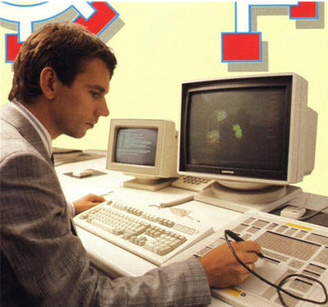 However, the enormous value came from making changes, the easy way of sharing drawings and the ease of reuse. The picture on the left is me in 1989, demonstrating AutoCAD with a custom-defined tablet and PS/2 computer.
The introduction of electronic drawings was not a disruption, more optimization of the previous ways of working.
The exchange with suppliers and manufacturing could still be based on plotted drawings – the most neutral format. And thanks to the filename, there was better control of versions between all stakeholders.
Aren’t we all happy?
The introduction of mainstream 3D CAD
 In 1995, 3D CAD became available for the mid-market, thanks to SolidWorks, Solid Edge and a little later Inventor. Before that working with 3D CAD was only possible for companies that could afford expensive graphic stations, provided by IBM, Silicon Graphics, DEC and SUN. Where are they nowadays? The PC is an example of disruptive innovation, purely based on technology. See Clayton Christensen’s famous book: The Innovator’s Dilemma.
The introduction of 3D CAD on PCs in the mid-market did not lead directly to new ways of working. Designing a product in 3D was much more efficient if you mastered the skills. 3D brought a better understanding of the product dimensions and shape, reducing the number of interpretation errors.
 Still, (electronic) drawings were the contractual deliverable when interacting with suppliers and manufacturing. As students were more and more trained with the 3D CAD tools, the traditional art of the draftsman disappeared.
3D CAD introduced some new topics to solve.
- First of all, a 3D CAD Assembly in the system was a collection of separate files, subassemblies, parts, and drawings that relate to each other with a specific version. So how to ensure the final assembly drawings were based on the correct part revisions? Companies were solving this by either using intelligent filenames (with revisions) or by using a PDM system where the database of the PDM system managed all the relations and their status.
- The second point was that the 3D CAD assembly also introduced a new feature, the product structure, or the “Bill of Materials”. This logical structure of the assembly up resembled a lot of the Bill of Material of the product. You could even browse deeper levels, which was not the case in the traditional Bill of Material on a drawing.
Note: The concept of EBOM and MBOM was not known in most companies. People were talking about the BOM as a one-level definition of parts or subassemblies in the assembly. See my Where is the MBOM? Post from July 2008 when this topic was still under discussion.
- The third point that would have a more significant impact later is that parts and assemblies could be reused in other products. This introduced the complexity of configuration management. For example, a 3D CAD part or assembly file could contain several configurations where only one configuration would be valid for the given product. Managing this in the 3D CAD system lead to higher productivity of the designer, however downstream when it came to data management with PDM systems, it became a nightmare.

I experienced these issues a lot when discussing with companies and implementers, mainly the implementation of SmarTeam combined with SolidWorks and Inventor. Where to manage the configuration constraints? In the PDM system or inside the 3D CAD system.
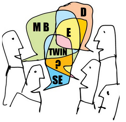
These environments were not friends (image above), and even if they came from the same vendor, it felt like discussing with tribes.
The third point also covered another topic. So far, CAD had been the first step for the detailed design of a product. However, companies now had an existing Bill of Material in the system thanks to the PDM systems. It could be a Bill of Material of a sub-assembly that is used in many other products.
Configuring a product no longer started from CAD; it started from a Product or Bill of Material structure. Sales and Engineers identified the changes needed on the BoM, keeping as much as possible released information untouched. This led to a new best practice.
The item-centric approach
 Around 2005, five years after introducing the term Product Lifecycle Management, slowly, a new approach became the standard. Product Lifecycle Management was initially introduced to connect engineering and manufacturing, driven by the automotive and aerospace industry.
It was with PLM that concepts as EBOM and MBOM became visible.
In particular, the EBOM was closely linked to engineering practices, i.e., modularity and reuse. The EBOM and its related information represented the product as it was specified. It is essential to realize that the parts in the EBOM could be generic specified purchase parts to be resolved when producing the product or that the EBOM contained Make-parts specified by drawings.
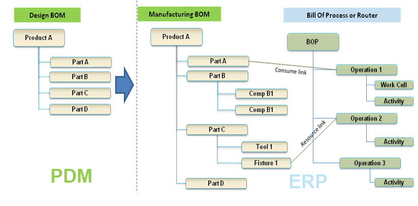
At that time, the EBOM was often used as the foundation for the ERP system – see image above. The BOM was restructured and organized according to the manufacturing process specifying materials and resources needed in the ERP system. Therefore, although it was an item-like structure, this BOM (the MBOM) always had a close relation to the Bill of Process.
For companies with a single manufacturing site, the notion of EBOM and MBOM was not that big, as the ERP system would be the source of the MBOM. However, the complexity came when companies have several manufacturing sites. That was when a generic MBOM in the PLM system made more sense to centralize all product information in a single system.
The EBOM-MBOM approach has become more and more a standard practice since 2010. As a result, even small and medium-sized enterprises realized a need to manage the EBOM and the MBOM.
There were two disadvantages introduced with this EBOM-MBOM approach.
- First, the EBOM and the MBOM as information structures require a lot of administrative maintenance if information needs to be always correct (and that is the CM target). Some try to simplify this by keeping the EBOM part the same as the MBOM part, meaning the EBOM specification already targets a single supplier or manufacturer.
- The second disadvantage of making every item in the BOM behave like a part creates inefficiencies in modern environments. Products are a mix of hardware(parts) and software(models/behavior). This BOM-centric view does not provide the proper infrastructure for a data-driven approach as part specifications are still done in drawings. We need 3D annotated models related to all kinds of other behavior and physical models to specify a product that contains hard-and software.
 A new paradigm is needed to manage this mix efficiently, the enabling foundation for Industry 4.0 and efficient Digital Twins; there is a need for a model-based approach based on connected data elements.
More next week.
Conclusion
| The age of paper drawings | 1960 – now dead |
| The age of electronic drawings | 1982 – potentially dead in 2030 |
| The mainstream 3D CAD | 1995 – to be evolving through MBD and MBSE to the future – not dead shortly |
| Item-centric approach | 2005 – to be evolving to a connected model-based approach – not dead shortly |
After the first article discussing “The Future of PLM,” now again a post in the category of PLM and complementary practices/domains a topic that is already for a long time on the radar: Model-Based Definition, I am glad to catch up with Jennifer Herron, founder of Action Engineering, who is one of the thought leaders related to Model-Based Definition (MBD) and Model-Based Enterprise (MBE).

In 2016 I spoke with Jennifer after reading her book: “Re-Use Your CAD – The Model-Based CAD Handbook”. At that time, the discussion was initiated through two articles on Engineering.com. Action Engineering introduced OSCAR seven years later as the next step towards learning and understanding the benefits of Model-Based Definition.
Therefore, it is a perfect moment to catch up with Jennifer. Let’s start.
Model-Based Definition
 Jennifer, first of all, can you bring some clarity in terminology. When I discussed the various model-based approaches, the first response I got was that model-based is all about 3D Models and that a lot of the TLA’s are just marketing terminology.
Can you clarify which parts of the model-based enterprise you focus on and with the proper TLA’s?
 Model-Based means many things to many different viewpoints and systems of interest. All these perspectives lead us down many rabbit holes, and we are often left confused when first exposed to the big concepts of model-based.
At Action Engineering, we focus on Model-Based Definition (MBD), which uses and re-uses 3D data (CAD models) in design, fabrication, and inspection.
There are other model-based approaches, and the use of the word “model” is always a challenge to define within the proper context.
For MBD, a model is 3D CAD data that comes in both native and neutral formats

Another model-based approach is Model-Based Systems Engineering (MBSE). The term “model” in this context is a formalized application of modeling to support system requirements, design, analysis, verification and validation activities beginning in the conceptual design phase and continuing throughout development and later lifecycle phases.
<Jos> I will come back on Model-Based Systems Engineering in future posts
Sometimes MBSE is about designing widgets, and often it is about representing the entire system and the business operations. For MBD, we often focus our education on the ASME Y14.47 definition that MBD is an annotated model and associated data elements that define the product without a drawing.
Model-Based Definition for Everybody?
I believe it took many years till 3D CAD design became a commodity; however, I still see the disconnected 2D drawing used to specify a product or part for manufacturing or suppliers. What are the benefits of model-based definition?
Are there companies that will not benefit from the model-based definition?
There’s no question that the manufacturing industry is addicted to their drawings. There are many reasons why, and yet mostly the problem is lack of awareness of how 3D CAD data can make design, fabrication, and inspection work easier.
 For most, the person doing an inspection in the shipping and receiving department doesn’t have exposure to 3D data, and the only thing they have is a tabulated ERP database and maybe a drawing to read. If you plop down a 3D viewable that they can spin and zoom, they may not know how that relates to their job or what you want them to do differently.
Today’s approach of engineering championing MBD alone doesn’t work. To evolve information from the 2D drawing onto the 3D CAD model without engaging the stakeholders (machinists, assembly technicians, and inspectors) never yields a return on investment.
Organizations that succeed in transitioning to MBD are considering and incorporating all departments that touch the drawing today.
Incorporating all departments requires a vision from the management. Can you give some examples of companies that have transitioned to MBD, and what were the benefits they noticed?
I’ll give you an example of a small company with no First Article Inspection (FAI) regulatory requirements and a huge company with very rigorous FAI requirements.
Note: click on the images below to enjoy the details.
 The small company instituted a system of CAD modeling discipline that allowed them to push 3D viewable information directly to the factory floor. The assembly technicians instantly understood engineering’s requirements faster and better.
The positive MBD messages for these use cases are 3D navigation, CAD Re-Use, and better control of their revisions on the factory floor.
 The large company has added inspection requirements directly onto their engineering and created a Bill of Characteristics (BOC) for the suppliers and internal manufacturers. They are removing engineering ambiguity, resulting in direct digital information exchange between engineering, manufacturing, and quality siloes.
These practices have reduced error and reduced time to market.
The positive MBD messages for these use cases are unambiguous requirements capture by Engineering, Quality Traceability, and Model-Based PMI (Product and Manufacturing Information).
Model-Based Definition and PLM?
How do you see the relation between Model-Based Definition and PLM? Is a PLM system a complication or aid to implement a Model-Based Definition? And do you see a difference between the old and new PLM Vendors?
Model-Based Definition data is complex and rich in connected information, and we want it to be. With that amount of connected data, a data management system (beyond upload/download of documents) must keep all that data straight.
Depending on the size and function of an organization, a PLM may not be needed. However, a way to manage changes and collaboration amongst those using 3D data is necessary. Sometimes that results in a less sophisticated Product Data Management (PDM) system. Large organizations often require PLM.
 There is significant resistance to doing MBD and PLM implementations simultaneously because PLM is always over budget and behind schedule. However, doing just MBD or just PLM without the other doesn’t work either. I think you should be brave and do both at once.
I think we can debate why PLM is always over budget and behind schedule. I hear the same about ERP implementations. Perhaps it has to deal with the fact that enterprise applications have to satisfy many users?
I believe that working with model versions and file versions can get mixed in larger organizations, so there is a need for PDM or PLM. Have you seen successful implementations of both interacting together?
Yes, the only successful MBD implementations are those that already have a matured PDM/PLM (scaled best to the individual business).
Model-Based Definition and Digital Transformation
In the previous question, we already touched on the challenge of old and modern PLM. How do you see the introduction of Model-Based Definition addressing the dreams of Industry 4.0, the Digital Twin and other digital concepts?
I just gave a presentation at the ASME Digital Twin Summit discussing the importance of MBD for the Digital Twin. MBD is a foundational element that allows engineering to compare their design requirements to the quality inspection results of digital twin data.
The feedback loop between Engineering and Quality is fraught with labor-intensive efforts in most businesses today.
Leveraging the combination of MBD and Digital Twin allows automation possibilities to speed up and increase the accuracy of the engineering to inspection feedback loop. That capability helps organizations realize the vision of Industry 4.0.
And then there is OSCAR.
I noticed you announced OSCAR. First, I thought OSCAR was a virtual aid for model-based definition, and I liked the launching page HERE. Can you tell us more about what makes OSCAR unique?
One thing that is hard with MBD implementation is there is so much to know. Our MBDers at Action Engineering have been involved with MBD for many years and with many companies. We are embedded in real-life transitions from using drawings to using models.
Suppose you start down the model-based path for digital manufacturing. In that case, there are significant investments in time to learn how to get to the right set of capabilities and the right implementation plan guided by a strategic focus. OSCAR reduces that ramp-up time with educational resources and provides vetted and repeatable methods for an MBD implementation.
![]() OSCAR combines decades of Action Engineering expertise and lessons learned into a multi-media textbook of sorts. To kickstart an individual or an organization’s MBD journey, it includes asynchronous learning, downloadable resources, and CAD examples available in Creo, NX, and SOLIDWORKS formats.
OSCAR combines decades of Action Engineering expertise and lessons learned into a multi-media textbook of sorts. To kickstart an individual or an organization’s MBD journey, it includes asynchronous learning, downloadable resources, and CAD examples available in Creo, NX, and SOLIDWORKS formats.
CAD users can access how-to training and downloadable resources such as the latest edition of Re-Use Your CAD (RUYC). OSCAR enables process improvement champions to make their case to start the MBD journey. We add content regularly and post what’s new. Free trials are available to check out the online platform.
Learn more about what OSCAR is here:
Want to learn more?
In this post, I believe we only touched the tip of the iceberg. There is so much to learn and understand. What would you recommend to a reader of this blog who got interested?
RUYC (Re-Use Your CAD) is an excellent place to start, but if you need more audio-visual, and want to see real-life examples of MBD in action, get a Training subscription of OSCAR to get rooted in the vocabulary and benefits of MBD with a Model-Based Enterprise. Watch the videos multiple times! That’s what they are for. We love to work with European companies and would love to support you with a kickstart coaching package to get started.
What I learned
First of all, I learned that Jennifer is a very pragmatic person. Her company (Action Engineering) and her experience are a perfect pivot point for those who want to learn and understand more about Model-Based Definition. In particular, in the US, given her strong involvement in the American Society of Mechanical Engineers (ASME).
I am still curious if European or Asian counterparts exist to introduce and explain the benefits and usage of Model-Based Definition to their customers. Feel free to comment.
Next, and an important observation too, is the fact that Jennifer also describes the tension between Model-Based Definition and PLM. Current PLM systems might be too rigid to support end-to-end scenarios, taking benefit of the Model-Based definition.
 I have to agree here. PLM Vendors mainly support their own MBD (model-based definition), where the ultimate purpose is to share all product-related information using various models as the main information carriers efficiently.
We have to study and solve a topic in the PLM domain, as I described in my technical highlights from the PLM Road Map & PDT Spring 2021 conference.
There is work to do!
Conclusion
Model-Based Definition is, for me, one of the must-do steps of a company to understand the model-based future. A model-based future sometimes incorporates Model-Based Systems Engineering, a real Digital Thread and one or more Digital Twins (depending on your company’s products).
It is a must-do activity because companies must transform themselves to depend on digital processes and digital continuity of data to remain competitive. Document-driven processes relying on the interpretation of a person are not sustainable.
After the first article discussing “The Future of PLM,” now again a post in the category of PLM and complementary practices/domains a topic that is already for a long time on the radar: Model-Based Definition, I am glad to catch up with Jennifer Herron, founder of Action Engineering, who is one of the thought leaders related to Model-Based Definition (MBD) and Model-Based Enterprise (MBE).
In 2016 I spoke with Jennifer after reading her book: “Re-Use Your CAD – The Model-Based CAD Handbook”. At that time, the discussion was initiated through two articles on Engineering.com. Action Engineering introduced OSCAR seven years later as the next step towards learning and understanding the benefits of Model-Based Definition.
Therefore, it is a perfect moment to catch up with Jennifer. Let’s start.
Model-Based Definition
Jennifer, first of all, can you bring some clarity in terminology. When I discussed the various model-based approaches, the first response I got was that model-based is all about 3D Models and that a lot of the TLA’s are just marketing terminology.
Can you clarify which parts of the model-based enterprise you focus on and with the proper TLA’s?
Model-Based means many things to many different viewpoints and systems of interest. All these perspectives lead us down many rabbit holes, and we are often left confused when first exposed to the big concepts of model-based.
At Action Engineering, we focus on Model-Based Definition (MBD), which uses and re-uses 3D data (CAD models) in design, fabrication, and inspection.
There are other model-based approaches, and the use of the word “model” is always a challenge to define within the proper context.
For MBD, a model is 3D CAD data that comes in both native and neutral formats
Another model-based approach is Model-Based Systems Engineering (MBSE). The term “model” in this context is a formalized application of modeling to support system requirements, design, analysis, verification and validation activities beginning in the conceptual design phase and continuing throughout development and later lifecycle phases.
<Jos> I will come back on Model-Based Systems Engineering in future posts
Sometimes MBSE is about designing widgets, and often it is about representing the entire system and the business operations. For MBD, we often focus our education on the ASME Y14.47 definition that MBD is an annotated model and associated data elements that define the product without a drawing.
Model-Based Definition for Everybody?
I believe it took many years till 3D CAD design became a commodity; however, I still see the disconnected 2D drawing used to specify a product or part for manufacturing or suppliers. What are the benefits of model-based definition?
Are there companies that will not benefit from the model-based definition?
There’s no question that the manufacturing industry is addicted to their drawings. There are many reasons why, and yet mostly the problem is lack of awareness of how 3D CAD data can make design, fabrication, and inspection work easier.
For most, the person doing an inspection in the shipping and receiving department doesn’t have exposure to 3D data, and the only thing they have is a tabulated ERP database and maybe a drawing to read. If you plop down a 3D viewable that they can spin and zoom, they may not know how that relates to their job or what you want them to do differently.
Today’s approach of engineering championing MBD alone doesn’t work. To evolve information from the 2D drawing onto the 3D CAD model without engaging the stakeholders (machinists, assembly technicians, and inspectors) never yields a return on investment.
Organizations that succeed in transitioning to MBD are considering and incorporating all departments that touch the drawing today.
Incorporating all departments requires a vision from the management. Can you give some examples of companies that have transitioned to MBD, and what were the benefits they noticed?
I’ll give you an example of a small company with no First Article Inspection (FAI) regulatory requirements and a huge company with very rigorous FAI requirements.
Note: click on the images below to enjoy the details.
The small company instituted a system of CAD modeling discipline that allowed them to push 3D viewable information directly to the factory floor. The assembly technicians instantly understood engineering’s requirements faster and better.
The positive MBD messages for these use cases are 3D navigation, CAD Re-Use, and better control of their revisions on the factory floor.
The large company has added inspection requirements directly onto their engineering and created a Bill of Characteristics (BOC) for the suppliers and internal manufacturers. They are removing engineering ambiguity, resulting in direct digital information exchange between engineering, manufacturing, and quality siloes.
These practices have reduced error and reduced time to market.
The positive MBD messages for these use cases are unambiguous requirements capture by Engineering, Quality Traceability, and Model-Based PMI (Product and Manufacturing Information).
Model-Based Definition and PLM?
How do you see the relation between Model-Based Definition and PLM? Is a PLM system a complication or aid to implement a Model-Based Definition? And do you see a difference between the old and new PLM Vendors?
Model-Based Definition data is complex and rich in connected information, and we want it to be. With that amount of connected data, a data management system (beyond upload/download of documents) must keep all that data straight.
Depending on the size and function of an organization, a PLM may not be needed. However, a way to manage changes and collaboration amongst those using 3D data is necessary. Sometimes that results in a less sophisticated Product Data Management (PDM) system. Large organizations often require PLM.
There is significant resistance to doing MBD and PLM implementations simultaneously because PLM is always over budget and behind schedule. However, doing just MBD or just PLM without the other doesn’t work either. I think you should be brave and do both at once.
I think we can debate why PLM is always over budget and behind schedule. I hear the same about ERP implementations. Perhaps it has to deal with the fact that enterprise applications have to satisfy many users?
I believe that working with model versions and file versions can get mixed in larger organizations, so there is a need for PDM or PLM. Have you seen successful implementations of both interacting together?
Yes, the only successful MBD implementations are those that already have a matured PDM/PLM (scaled best to the individual business).
Model-Based Definition and Digital Transformation
In the previous question, we already touched on the challenge of old and modern PLM. How do you see the introduction of Model-Based Definition addressing the dreams of Industry 4.0, the Digital Twin and other digital concepts?
I just gave a presentation at the ASME Digital Twin Summit discussing the importance of MBD for the Digital Twin. MBD is a foundational element that allows engineering to compare their design requirements to the quality inspection results of digital twin data.
The feedback loop between Engineering and Quality is fraught with labor-intensive efforts in most businesses today.
Leveraging the combination of MBD and Digital Twin allows automation possibilities to speed up and increase the accuracy of the engineering to inspection feedback loop. That capability helps organizations realize the vision of Industry 4.0.
And then there is OSCAR.
I noticed you announced OSCAR. First, I thought OSCAR was a virtual aid for model-based definition, and I liked the launching page HERE. Can you tell us more about what makes OSCAR unique?
One thing that is hard with MBD implementation is there is so much to know. Our MBDers at Action Engineering have been involved with MBD for many years and with many companies. We are embedded in real-life transitions from using drawings to using models.
Suppose you start down the model-based path for digital manufacturing. In that case, there are significant investments in time to learn how to get to the right set of capabilities and the right implementation plan guided by a strategic focus. OSCAR reduces that ramp-up time with educational resources and provides vetted and repeatable methods for an MBD implementation.
![]() OSCAR combines decades of Action Engineering expertise and lessons learned into a multi-media textbook of sorts. To kickstart an individual or an organization’s MBD journey, it includes asynchronous learning, downloadable resources, and CAD examples available in Creo, NX, and SOLIDWORKS formats.
OSCAR combines decades of Action Engineering expertise and lessons learned into a multi-media textbook of sorts. To kickstart an individual or an organization’s MBD journey, it includes asynchronous learning, downloadable resources, and CAD examples available in Creo, NX, and SOLIDWORKS formats.
CAD users can access how-to training and downloadable resources such as the latest edition of Re-Use Your CAD (RUYC). OSCAR enables process improvement champions to make their case to start the MBD journey. We add content regularly and post what’s new. Free trials are available to check out the online platform.
Learn more about what OSCAR is here:
Want to learn more?
In this post, I believe we only touched the tip of the iceberg. There is so much to learn and understand. What would you recommend to a reader of this blog who got interested?
RUYC (Re-Use Your CAD) is an excellent place to start, but if you need more audio-visual, and want to see real-life examples of MBD in action, get a Training subscription of OSCAR to get rooted in the vocabulary and benefits of MBD with a Model-Based Enterprise. Watch the videos multiple times! That’s what they are for. We love to work with European companies and would love to support you with a kickstart coaching package to get started.
What I learned
First of all, I learned that Jennifer is a very pragmatic person. Her company (Action Engineering) and her experience are a perfect pivot point for those who want to learn and understand more about Model-Based Definition. In particular, in the US, given her strong involvement in the American Society of Mechanical Engineers (ASME).
I am still curious if European or Asian counterparts exist to introduce and explain the benefits and usage of Model-Based Definition to their customers. Feel free to comment.
Next, and an important observation too, is the fact that Jennifer also describes the tension between Model-Based Definition and PLM. Current PLM systems might be too rigid to support end-to-end scenarios, taking benefit of the Model-Based definition.
I have to agree here. PLM Vendors mainly support their own MBD (model-based definition), where the ultimate purpose is to share all product-related information using various models as the main information carriers efficiently.
We have to study and solve a topic in the PLM domain, as I described in my technical highlights from the PLM Road Map & PDT Spring 2021 conference.
There is work to do!
Conclusion
Model-Based Definition is, for me, one of the must-do steps of a company to understand the model-based future. A model-based future sometimes incorporates Model-Based Systems Engineering, a real Digital Thread and one or more Digital Twins (depending on your company’s products).
It is a must-do activity because companies must transform themselves to depend on digital processes and digital continuity of data to remain competitive. Document-driven processes relying on the interpretation of a person are not sustainable.
 I am still digesting all the content of the latest PLM Roadmap / PDT Fall 2020 conference and the new reality that starts to appear due to COVID-19. There is one common theme:
The importance of a resilient and digital supply chain.
Most PLM implementations focus on aligning disciplines internally; the supply chain’s involvement has always been the next step. Perhaps now it is time to make it the first step? Let’s analyze.
No Time to Market improvement due to disconnected supply chains?
During the virtual fireplace chat at the PLM Roadmap/PDT conference, just as a small bonus. You can read the full story here – the quote:
Marc mentioned a survey Gartner has done with companies in fast-moving industries related to the benefits of PLM. Companies reported improvements in accuracy of product data and product development. They did not see so much a reduced time to market or reduced product development costs. After analysis, Gartner believes the real issue is related to collaboration processes and supply chain practices. Here lead times did not change, nor the number of changes.
Of course, he spoke about fast-moving industries where the interaction was done in a disconnected manner. Gartner believes that the cloud would, for sure, start creating these benefits of a reduced time to market and cost of change when the supply chain is connected.
 Therefore I want to point again to an old McKinsey article named The case for Digital Reinvention, published in February 2017. Here the authors looked at the various areas of investment in digital technologies and their ROI. See the image on the left for the areas investigated and the percentage of companies that invested in these areas at that time.
In the article, you will see the ROI analysis for these areas. For example, the marketing and distribution investments did not necessarily have a positive ROI when disconnected from other improvement areas. Digital supply chains were mentioned as the area with the potential highest ROI. However, another important message in the article for all these areas is: You need to have a complete digitization strategy. This is a point I fail to see in many companies. Often an area gets all the attention, however as it remains disconnected from the rest, the real efficiencies are not there. The McKinsey article ends with the conclusion that the digital winners at that time are the ones with bold strategies win:
we found a mismatch between today’s digital investments and the dimensions in which digitization is most significantly affecting revenue and profit growth. We also confirmed that winners invest more and more broadly and boldly than other companies do
The “connected” supply chain

Image: A&D Action Group – Global Collaboration
Of course, the traditional industries that invented PLM have invested in a kind of connected supply chain. However, is it really a connected supply chain? Aerospace and Defense companies had their supplier portals.
A supplier had to download their information or upload their designs combined with additional metadata.
These portals were completely bespoke and required on both sides “backbreaking” manual work to create, deliver, and validate the required exchange packages. The OEMs were driving the exchange process. More or less, by this custom approach, they made it difficult for suppliers to have their own PLM-environment. The downside of this approach was that the supplier had separate environments for each OEM.
 In 2006 I worked with SmarTeam on the concept of the “Supply Chain Express,” an offering that allowed a supplier to have their own environment using SmarTeam as a PDM/PLM-system the Supply Chain Express package to create an intelligent import and export package. The content was all based on files and configurable metadata based on the OEM-Supplier relation.
Some other PLM-vendors or implementers have built similar exchange solutions to connect the world of the OEM and the supplier.
The main characteristic was that it is file-based with custom metadata, often in an XML-format or otherwise using Excel as the metadata carrier.
In my terminology of Coordinated – Connected, this would be Coordinated and “old school.”
The “better connected” supply chain
As I mentioned in my previous post about the PLM Roadmap/PDT Fall conference, Katheryn Bell (Pratt & Whitney Canada) presented the progress of the A&D Global Collaboration workgroup. As part of the activities, they classified the collaboration between the OEM and the supplier in 3 levels, as you can see from the image:
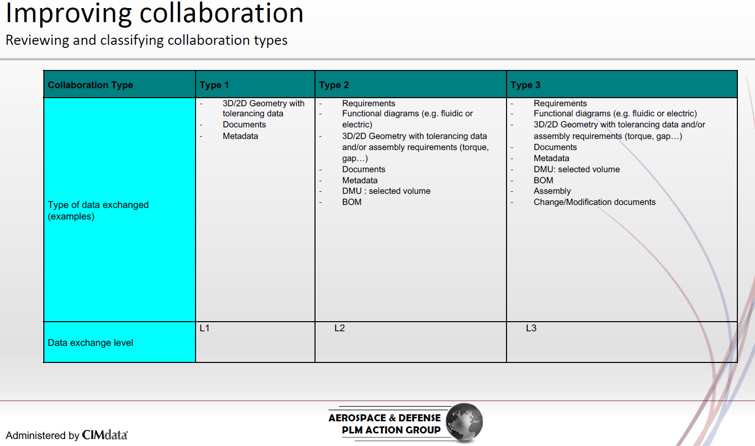
This post mainly focuses on the L1 collaboration as this is probably the most used scenario.
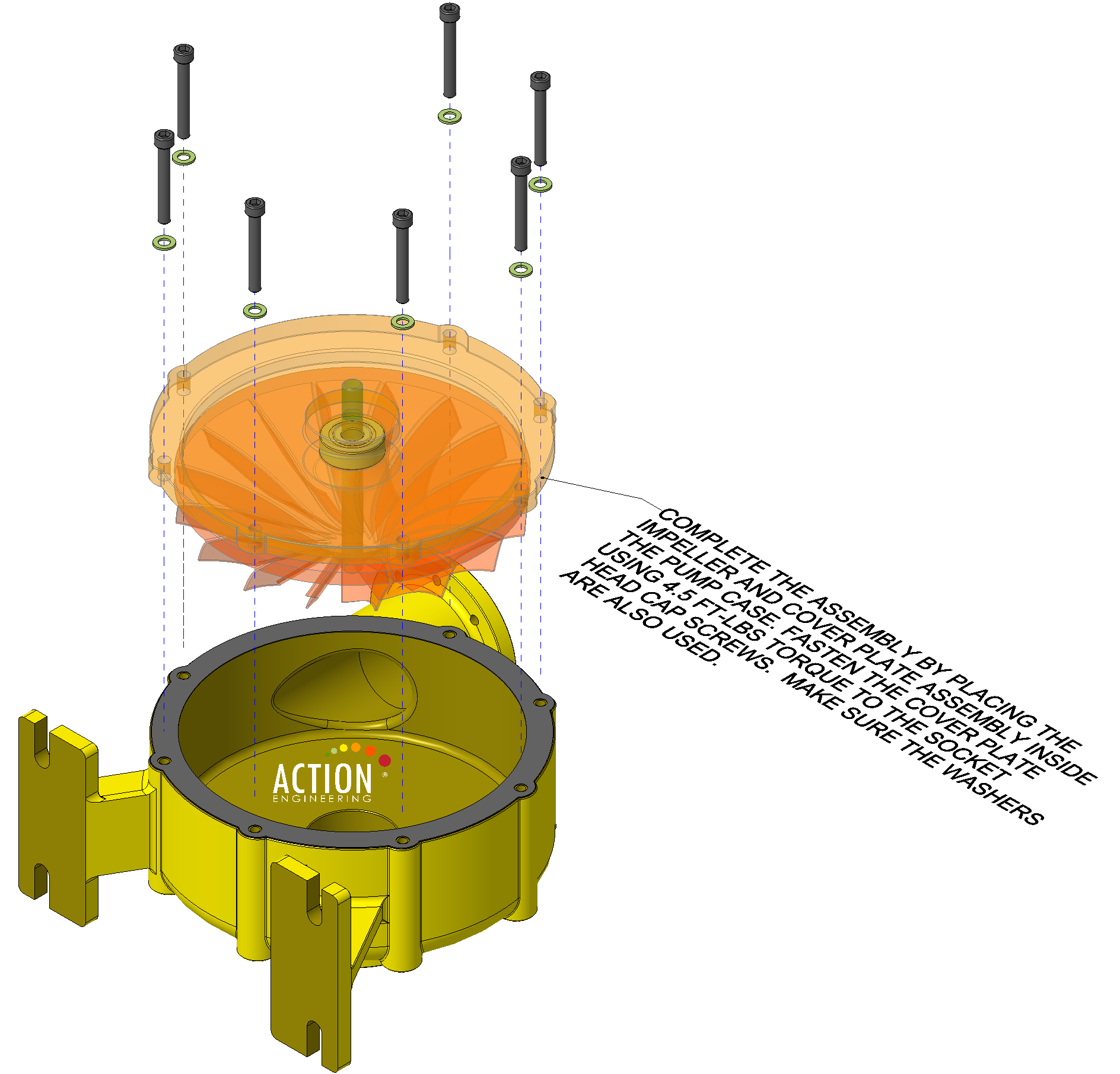
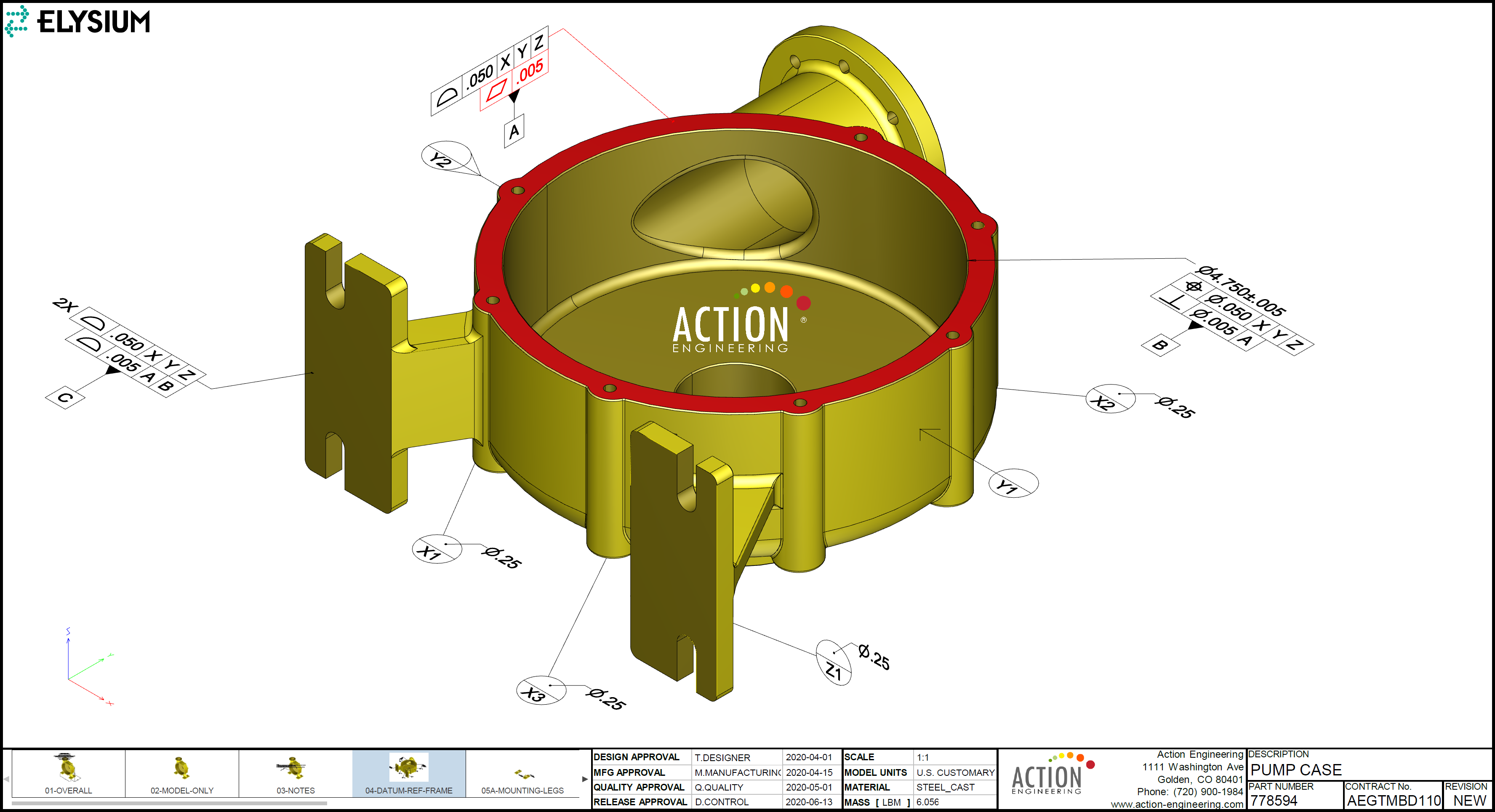
 In the Aerospace and Automotive industry, the OEM and suppliers’ data exchange has improved twofold by using Technical Data Packages where the content is supported by Model-Based Definition.
The first advantages of Model-Based Definition are mainly related to a consistent information package where the model is leading. The manufacturing views are explicitly defined on the 3D Model. Therefore there is a reduced chance of error for a misconnect between the “drawings” and the 3D Model.
The Model-Based definition still does not solve working with the latest (approved) version of the information. This still remains a “human-based” process in this case, and Kathryn Bell confirmed this was the biggest problem to solve.
The second advantage of using one of the interoperability standards for Model-Based Definition is the disconnect between application-specific data on the OEM side and the supplier side.
 A significant advantage of Model-Based Definition is that there are a few interoperability standards, i.e., ISO 10303 – STEP, ISO14306 – JT, and ISO32000/14739 (PRC for 3D PDF). In the end, the ideal would be that these standards merge into one standard, completely vendor-independent with a clearly defined scope of its purpose.
The benefit of these standards is also they increase the longevity of product data as the information is stored in an application-independent format. As long as the standard does not change (fast), storing data even internally in these neutral formats can save upgrade or maintenance costs.
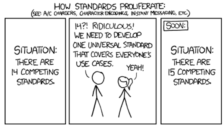
However, I think you all know the joke below.
The connected supply chain
The ultimate goal in the long term will be the connected supply chain. Information shared between an OEM, and a supplier does not require human-based interfaces to ensure everyone works with the correct data.
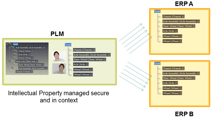
 The easiest way, and this is what some of the larger OEMs have done, is to consider suppliers as part of your PLM-infrastructure and give them access to all relevant data in the context of the system, the product, or the part they are responsible for. For the OEM, the challenge will be to connect suppliers – to motivate and train them to work in this environment.
For the supplier, the challenge is their IP-management. If they work for 100 percent in the OEM-environment, everything is exposed. If they want to work in their own environment, there is probably double work and a disconnect.
Of course, everything depends on the complexity of your interaction with the supplier.
With its Fusion Cloud Product Lifecycle Management (PLM), Oracle was one of the first to shift the attention to the connected supply chain.
 If you search for PLM on the Oracle website, you will find it under Fusion Supply Chain and Manufacturing. It is a logical step as traditional ERP-vendors have never provided a full, rich portfolio for product design. CAD-integrations do not get a focus, and the future path to Model-Bases approaches (MBSE / MBD /MBE) is not visible at all.
Almost similar to what the Siemens-SAP alliance is showing. SAP more or less confirms that you should not rely on SAP PLM for more advanced PLM-scenarios but on Siemens’s offering.
For less complex but fast-moving products, for example, in the apparel industry, you see the promise of connecting all suppliers in one environment is time to market and traceability. This industry does not suffer from products with a long lifecycle with upgrades and services.
So far, the best collaboration platform in the cloud I have seen in Shareaspace from Eurostep. Its foundation based on the PLCS standard allows an OEM and Supplier to connect through their “shared space” – you can look at their supply chain offering here.
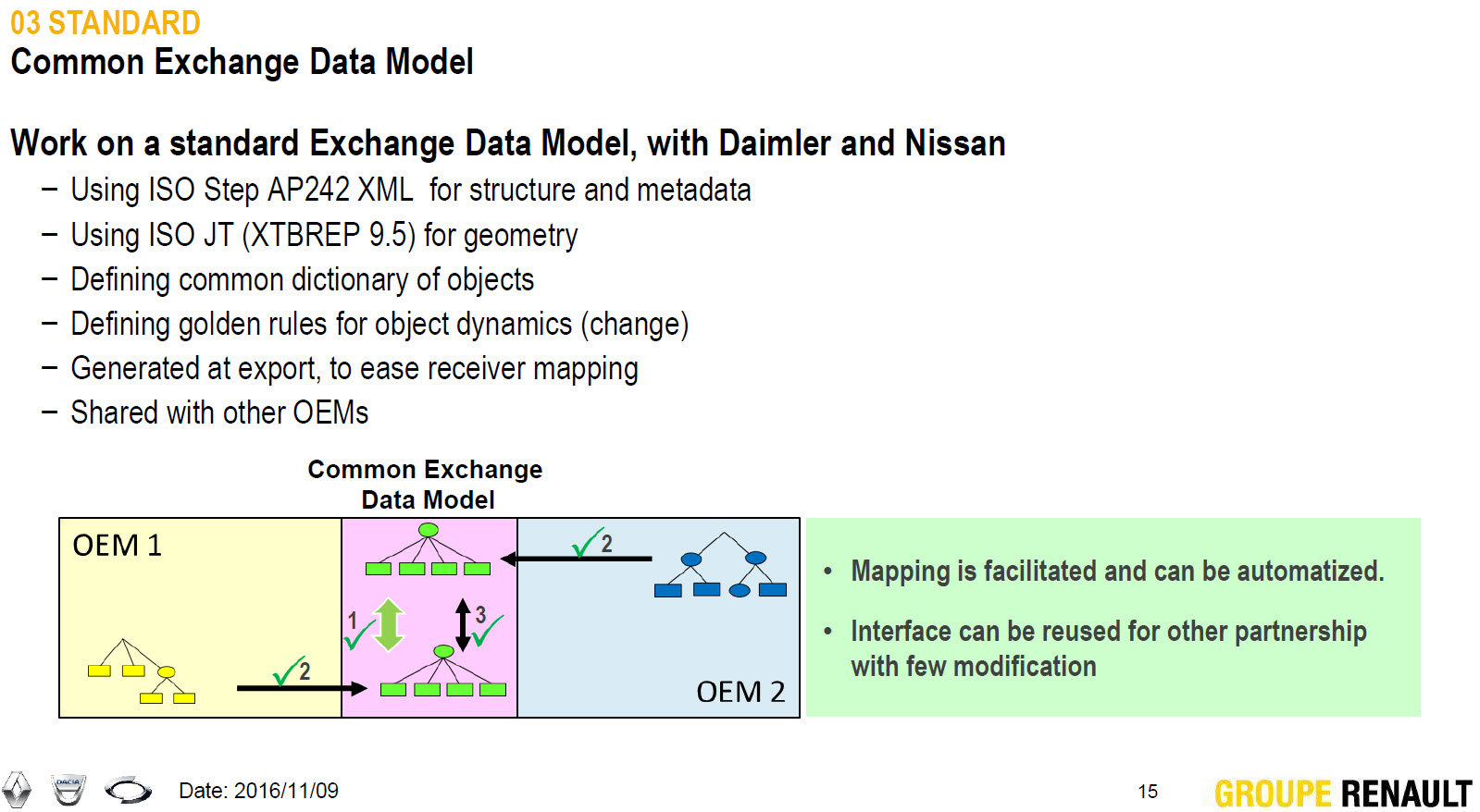
Slide: PDT Europe 2016 RENAULT PLM Challenges
In the various PDT-conferences, we have seen how even two OEMs could work in a joined environment (Renault-Nissan-Daimler) or how BAE Systems used the ShareAspace environment to collaborate and consolidate all the data coming from the various system suppliers into one standards-based environment.
In 2021, I plan to write a series of blog posts related to possible add-on services for PLM. Supplier collaboration platforms, Configuration Management, End-to-end configurators, Product Information Management, are some of the themes I am currently exploring.
Conclusion
COVID-19 has illustrated the volatility of supply chains. Changing suppliers, working with suppliers in the traditional ways, still hinder reducing time to market. However, the promise of a real connected supply chain is enormous. As Boeing demonstrated in my previous post and explained in this post, standards are needed to become future proof.
Will 2021 have more focus on the connected supply chain?
 Last time in the series Learning from the past to understand the future, we zoomed in on how the 3D CAD-structure in the mid-market had to evolve. In a typical Engineering To Order (ETO) scenario, it makes sense to extract from the 3D CAD-structure a BOM-structure to collect all the individual parts that are needed for manufacturing. Combined with the drawings generated based on the 3D CAD assemblies/parts, the complete manufacturing information could be provided. Let’s have a look.
The BOM in ERP (part 1)
To understand what most mid-market companies have been doing, I created the image below. When you click on it, you will have an enlarged version.
Note: for educational purposes an extremely simplified example
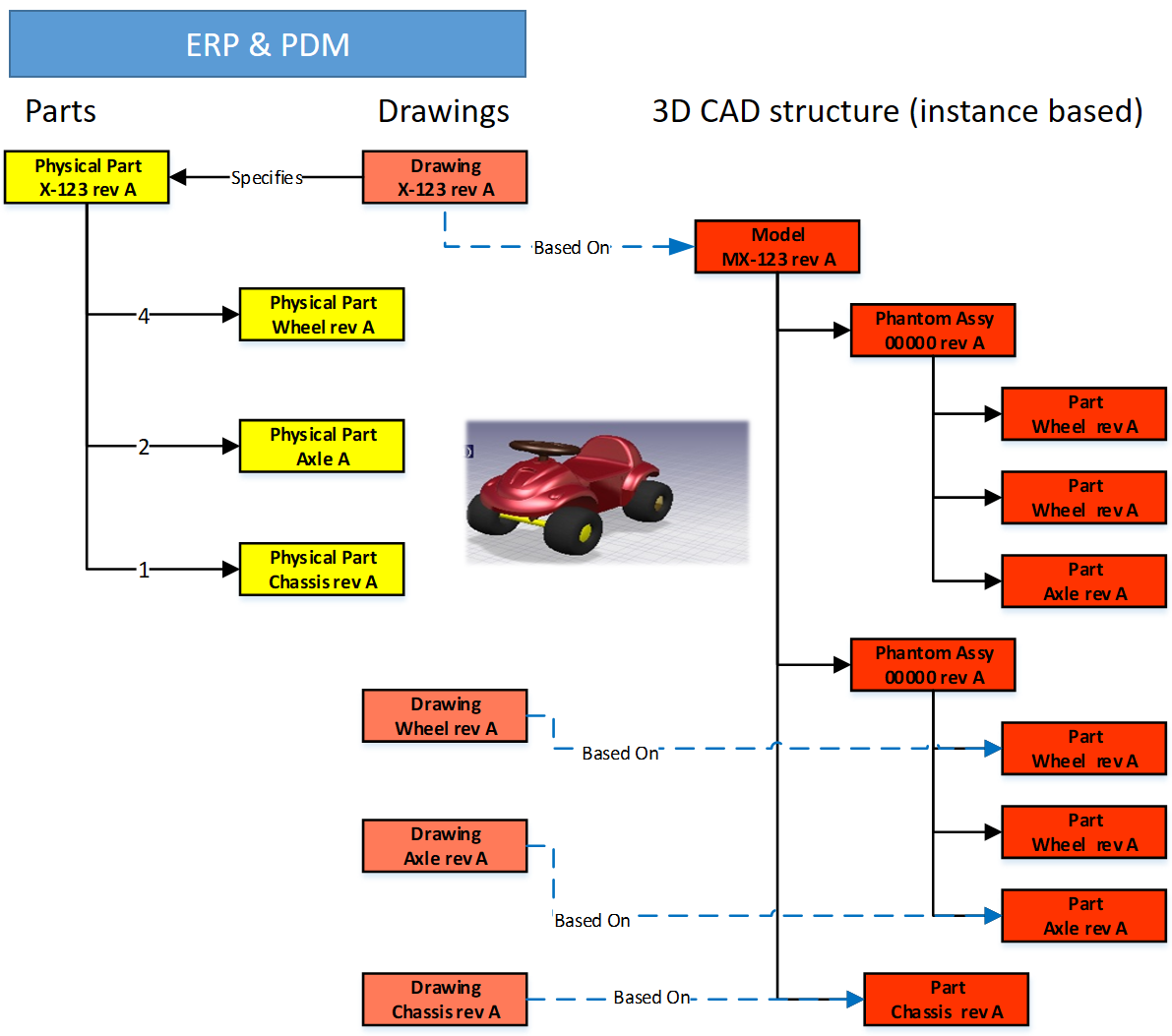
There is a lot to explain here.
First, on the right we see the 3D CAD assembly, two phantom assemblies, grouping the wheels and the axle. And at the end, the individual parts, i.e. chassis, axle, and wheel. The 3D CAD-structure is an instance-based structure; therefore, there are no quantities in the structure (all quantity 1)
For the individual parts, there are drawings. Also, for the product, we have an assembly drawing. The drawings are essential as we want to have them in the ERP-system for manufacturing.
Finally, the physical parts, now with a different ID than the drawing as we learned this one-to-one relation created a lot of extra work. The physical parts are often called Items or Materials (SAP naming). Unfortunately, for engineering, there is a different meaning behind Materials. Still, SAP’s data model was not built with an engineering mindset.
The physical part structure, which we call the BOM contains quantities. Most PDM-CAD-integrations can filter out phantom assemblies and summarize the parts on the same level
 I am still reluctant to call the Part-structure an EBOM as the design of the product has been mainly focusing on extracting manufacturing information, parts, and drawings.
The BOM in ERP (part 2)
In customized PDM-implementations, some implementers created an interface from the BOM-structure to ERP, so the ERP-system would have the basic definition of the parts and a copy of the relevant drawings.
Now manufacturing could create the manufacturing definition without the need to go into the PDM-system.
Some “clever” – Dick Bourke would say “smart – therefore lazy” – proposed to “draw” also manufacturing entities in the 3D CAD-structure, so the PDM-CAD-interface would automatically deliver manufacturing parts too inside the ERP. In the example below, we added paint for the body and grease needed for the axels.
Although “smart, a new problem was introduced here – the 3D CAD-structure, instance-based, always has quantities 1. The extracted BOM would have rounded numbers when considering design parts. Now the grease comes with an estimate of 0.025 kg, assuming quantities are based on SI-units. We could also add other manufacturing information to this BOM, like 0.3-liter paint. Anyway, the result would look like below:
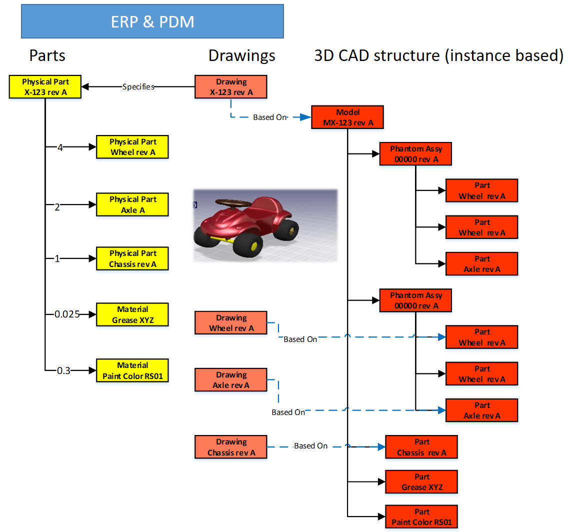
Important to notice from the diagram here: There are placeholders for grease and paint “drawn” in the 3D CAD-structure – parts without a geometrical definition and, therefore, not having an associated drawing. However, these parts have a material specification, and therefore in the BOM-structure, they appear as Materials.
Next in the BOM-structure, the engineers would enter the expected/required quantity – which is no longer a rounded number.
 At this stage, you cannot call the BOM on the left an EBOM. It is a kind of hybrid structure, combining engineering and manufacturing data. A type of BOM we discover a lot in companies that started with a type of ETO-product.
The ETO-product
 Many companies that developed specialized machinery have started with a base product, from where they developed the custom solution – their IP. Next, with more and more customers, the original solution was extended by creating either new or changed capabilities.
I worked a lot with companies that moved to the full definition of their products in 3D CAD, creating a correct 3D CAD-structure per customer order. Instead of creating new BOM variants, companies were often tempted/forced to make the configuration inside the 3D CAD-model.

Every time one of the configurations of the part would change, or a new configuration was added, the file has to be revised.
 And if the change was at level five of a 3D CAD-structure, many assembly files needed to be updated. The versioning problem illustrates the challenge of managing configurations inside a 3D CAD-file, meanwhile creating complexity for the PDM/PLM-system.
Last week Tech-Clarity published the highlights of their survey: Bringing Custom-Engineered Products to Market with a link to the full report, sponsored by Propel.
 As you can imagine, this survey is more about PLM collaboration, breaking down the silos and acting agile. Unfortunately, the report does not expose required methodologies, like modularity and “common sense” engineering practices that we discuss here. Still worthwhile to read as the report addresses precisely the type of companies I am referring too here.
If we look at the methodology of custom-engineered products, let us look at how their “best practice” from the past is blocking the future.
When a new customer request is coming in, sales engineering is looking for the best match of delivered products. Hopefully, 80-90 % remains the same, and engineering has to focus only on the differences.
 First, the best-match 3D CAD-structure is copied to a new project. As you can see most 3D CAD-systems provide the functionality to create a derived structure from an original 3D CAD-structure. From there, a traditional ETO-process starts as described at the beginning of this post. We complete the 3D CAD-structure with manufacturing in mind, generate the BOM and drawings, and we can deliver. In the case of purchase parts, the generated BOM often contains already the supplier part number in the 3D CAD-structure as we are focusing on this single delivery.
The disadvantage of this approach that in theory, we have to check if the structure that we reused is really the best so far, otherwise we introduce errors again.
 The second disadvantage is that if one supplier part in the structure becomes obsolete and needs to be revised, the company has to go through all the 3D CAD-structures to fix it.
Also, having supplier parts in the 3D CAD-structure makes it more difficult to standardize, as the chosen supplier part matched the criteria for that customer at that time. Will it match the criteria also in other situations?
From ETO to BTO to CTO
Many companies that started with custom-engineered products, the ETO-approach, want to move towards a Configure To Order (CTO) approach – or if not possible at least Build To Order (BTO). More reuse, less risk, instead of creating every time a new solution for the next customer, as discussed before.
This is not a mission impossible; however, often, I have seen that companies do not set the right priorities to move towards a configure to order environment. There are a few changes needed to become a configure to order company (if possible):
- Analyze your solution and define modules and options. Instead of defining a full solution, the target now is to discover a commonality between the various solutions. Based on commonality, define modules and options in such a manner that they can be used in different situations. Crucial for these modules is that there is a standard interface to the rest of the product. Every company needs to master this specific methodology for their products
- Start defining products from a logical structure, defining how products, modules and options are compatible and which combinations are allowed (or preferred). For companies that are not familiar with logical structure, often a configured EBOM is used to define the solutions. Not the optimal way; however, this was the first approach most companies took ten years ago. I will explain the configured EBOM below.
- A product definition and its modules now should start from a real EBOM, not containing manufacturing characteristics. The EBOM should represent the logical manner of how a product is defined. You will notice this type of EBOM might be only 2 – 3 levels deep. At the lowest level, you have the modules that have their own lifecycle and isolated definition.
- You should no longer use supplier part numbers in your EBOMs. As the engineering definition of a module or option should not depend over time from a single supplier. We will discuss in the next post the relation between EBOM parts and the Approved Manufacturer List (AML)
To conclude for today
Changing from ETO to CTO requires modularity and a BOM-driven approach. Starting from a 3D CAD-structure can still be done for the lowest levels – the modules, the options. In a configure to order process, it might not be relevant anymore to create a full 3D-representation of the product.
However, when we look forward, it would be greatly beneficial to have the 3D-representation of every specific solution delivered. This is where concepts as augmented/virtual reality and digital twin come in.
Next time more on the BOM-structures – as we have just touched the upcoming of the EBOM – enough to clarify next week(s).
In my last post related to Learning from the past to understand the future, I discussed what happened when 3D CAD became available for the mid-market. In the large automotive or aerospace & defense companies, 3D CAD has been introduced along the path of defining processes and selecting tools. In the mid-market 3D CAD started from the other side, first as a productivity tool, not thinking further to change methodologies or processes.
The approach starting with 3D CAD without changing processes, has created several complexities. Every company that is aiming to move towards a digital future needs to reduce complexity to remain competitive. Now let us focus on the relation between the 3D CAD-structure and a BOM.
The 3D CAD-structure
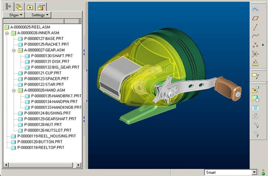 When building a product in a 3D CAD system, the concept is that you have individual parts designed in 3D. Every single part has a unique identifier.
If possible, the (file) name would equal the physical part number.
Next, a group of parts could be stored as a subassembly. Such an assembly is sometimes called a phantom assembly, in case they only group together several 3D parts. The usage of this type of assemblies increased CAD productivity. For data management reasons, these assemblies need to have a unique identifier, preferably not with the same numbering scheme for physical part numbers. It would consume part numbers that would never be used during manufacturing.
Note: in the early days of connecting 3D CAD to ERP, there was a considerable debate about which system could generate the part number.
ERP has always been the leading system for parts definition, why change ? And why generate part numbers that might not be used later in production. “Wasting” part numbers was a bad practice as historically, the part number was like a catalog number: 6 to 7 digits.
 Next, there is also another group of subassemblies that represent one or more primary components of a product. For example, a pump assembly, that might be the combination of the pump, the motor, and the base frame. This type of assembly appears most of the time high in the CAD-structure. They can be considered as a phantom assembly too, regarding a required identifier for this subassembly.
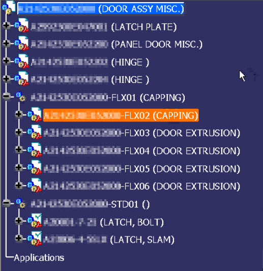 Finally, there might be parts in the CAD-structure that will not exist in reality as part but need to be created during the manufacturing process. Sheet metal parts are created during the manufacturing process. Cappings, strips and cables shown in the CAD-structure might come from materials that are purchased in standardized sizes (1 meter / 2 meter / 10 meter) and need to be cut during manufacturing. Here the instances in the CAD-structure will have a unique identifier. What type of identifier to use depends on the manufacturing process. It might be a physical part number, as it is a half-fabricate, or it remains a unique identifier for the CAD-structure only.
The reason I am coming back to these identifiers is that as described before, companies wanted to keep a relation between the part number and the file name.
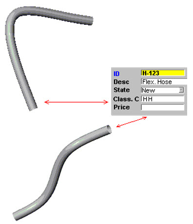 There was a problem with flexible parts. A rubber hose with a specific length could be shaped differently in an assembly based on its connection. Two different shapes would create two files and therefore break the rule of a part number equals file name. The 3D CAD vendors “solved” this issue by storing configurable views of the same part inside one file and allow the user to select the active view.
Later we will see that management of views inside the 3D CAD model is not a wrong choice. This, contrary to managing different configurations of a part/product inside a single file, which creates complexity in the PLM domain.
In the end, the product became an assembly with several levels of subassemblies. At that time, when I worked a lot with CAD-integrations, the average depth of 3D CAD-structures was 6 to 7 levels deep, with exceptions in both directions.
The entire product CAD-structure is mainly used for a final digital mock-up, to allow engineers to analyze the full product behavior. One of my favorite YouTube movies is the one from Airbus – seven years ago, they described the power of a full digital mock-up used for the A380.
In ETO-processes, the 3D CAD-structure is unique for a given customer solution – like the A380.
 In the case of large assemblies with a lot of parts and subassemblies, there were situations where the full product could not be resolved anymore. For Airbus a must, for the mid-market not always easy to reach. Graphics memory, combined with the way graphics were represented, are the major constraint. This performance issue is resolved in the gaming world, however then the 3D representation had no longer the required accuracy or definition.
The Version pop-up problem
 Working with a 3D CAD structure created a new problem when designers were sharing parts and assemblies between themselves and suppliers. The central storage of the files required a versioning mechanism, supported by a check-in and check-out mechanism.
Depending on the type of 3D CAD integration, the PDM system generated a new minor revision of the file after check-in again. In this way, there was full traceability of the changes before release. The image below shows an example of how SmarTeam was dealing with minor and major revisions combined with lifecycle stages.
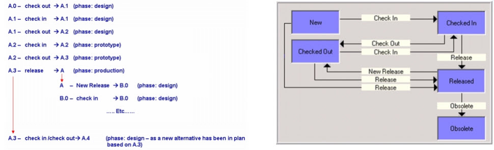
When revising a part, all assemblies that contained the changed part need to be updated too, in case you want to have traceability and preventing others from overwriting your version. Making sure this assembly file points to the right file again. In the cases of a 6-level deep CAD-structure, this has led to a lot of methodology problems on how to deal (or not to deal) with file changes.
In the case of a unique delivery for a customer, the ETO-process, the issue might not be so big. As everything in the 3D CAD-structure is work in progress, you only need to be sure during the release process of the 3D CAD-structure that all parts and assemblies are resolved to the latest version (and verified)
Making changes on an existing product is way more complicated, as assemblies are released, and parts exist in production. In that case, the Bill of Material is the leading structure to control the versions and the change impact, as we will see.
![]() Note: Most CAD- and PLM-vendors loved to show you their demos, where starting from the CAD-structure, a product gets created (the ETO-process). The reality is that most companies do not start from the CAD-structure, but from an existing Bill of Material. In 2010, I wrote a few posts, discussing the relation between CAD and the BOM:
Note: Most CAD- and PLM-vendors loved to show you their demos, where starting from the CAD-structure, a product gets created (the ETO-process). The reality is that most companies do not start from the CAD-structure, but from an existing Bill of Material. In 2010, I wrote a few posts, discussing the relation between CAD and the BOM:
to explain there is more than a CAD-driven scenario.
The EBOM
In most PDM-systems with CAD-integrations, it is possible to create a Bill of Materials from the 3D CAD-structure. The Bill of Materials will be based on the parts inside the 3D CAD-structure. There is often the option to filter out phantom assemblies.
The structures are not the same. The 3D CAD-structure is instance-based, where the extracted Bill of Materials will summarize the part quantities on the same level. See the image below. There are four Wheel instances in the CAD structure, in the EBOM-structure, we have only one Wheel reference with quantity 4.
I named the structure on the right the EBOM as the structure represents the Bill of Materials from the engineering point of view. This definition is a little arbitrary, as we will see. In companies that started to develop products based on a conceptual BOM, often, this conceptual BOM was an “early” EBOM that had to be developed further. This EBOM was more representing a logical or modular structure driving the design, instead of an extract from the 3D CAD-structure. In the next post, I will zoom in on these differences. I want to conclude this time with a critical methodology needed to manage the 3D CAD structure changes in relation to an EBOM.
Breaking the rule Drawing ID (Model ID) = Part ID
Although I have been writing mostly about the 3D CAD structure, I want to remind us that the 3D Model in the mid-market is mainly used for design purposes. The primary delivery for manufacturing or a supplier is still a 2D-drawing for most companies. The 3D Model might be “nice to have” for CAM- or quality usage. Still, in case of a dispute, the 2D Drawing will be leading.
For that reason, in many mid-market companies, there was the following relation below:
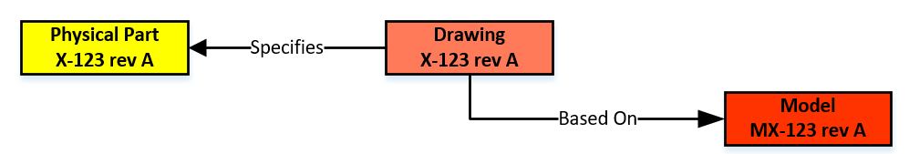
In an environment without file versioning through check-in/check-out, this relation was easy to maintain. In the electronic world, every change in the 3D Model (which could be an assembly) triggers a new file version and, therefore, most of the time, a new version of the drawing and the physical part. However, you do not want to have a physical part with many revisions, in particular when this part could be again part of a Bill of Material.
 To solve this issue, the Physical Part and the related Drawing/Model should have different lifecycles. The relation between the Physical Part and the Drawing Model should no longer be based on numbers but on a relation in the PDM/PLM-system. One of the main characteristics of a PDM/PLM-system is that it allows users to navigate through relations to find information in context. For example, solving a Where Used – question is a (few) mouse-click(s) in a PDM/PLM-system.
Click on the image to see the details.
Breaking this one-to-one numbering rule is a must if you want to evolve to an item-centric or data-driven PLM-environment. When to introduce this change and how to implement this new behavior is a methodology exercise, not an implementation of a new tool.
 There is a lot to read about this topic as it is related to the Form-Fit-Function-discussion we had earlier this year. A collection of information can be found in these two LinkedIn-post, where the comments are providing the insights:
- What the FFF is happening
- How to step beyond the complexity of Bill of Materials, Revisions and Change Management
I will not dive deeper into this theme (reached 1700 words ☹) – next time I will zoom in on the EBOM and leave the world of 3D CAD behind (for a while)
 To understand our legacy in the PLM-domain, what are the types of practices we created, I started this series of posts: Learning from the past to understand the future. My first post (The evolution of the BOM) focused on the disconnected world between engineering – generation of drawings as a deliverable – and execution MRP/ERP – the first serious IT-systems in a company.
At that time, due to minimal connectivity, small and medium-sized companies had, most of the time, an informal connection between engineering and manufacturing. I remember a statement at that time, PLM was just introduced. One person during a conference claimed:
“You guys make our lives so difficult with your systems. If we have a problem, we gather around the machine, and we fix it.”
PLM started at large enterprises
Of course, large enterprises could not afford such behavior as they operate globally. The leading enterprises for PDM/PLM were the Aerospace & Defense and Automotive companies. They needed consistent processes and formal ways of working to guarantee quality output.
 In that sense, I was happy with the reaction from Jean-Jacques Urban-Galindo, who shared in the LinkedIn comments a reference to a relevant chapter of John Stark’s PLM book. In the pdf describing the evolution of CAD / PDM / PLM at PSA. Jean-Jacques was responsible at that time for Responsible for the re-engineering of the Product & Process Engineering processes using digital tools (CAD/CAM, DMU, and more).
Read the PSA story here: PLM at GROUPE PSA. It describes nicely where 3D CAD and EBOM are coming in. In large enterprise like PSA, the need for tools are driven by the processes. When you read it to the end, you will also see the need for a design and a manufacturing view. A topic I will touch in future posts too.
The introduction of 3D CAD in the mid-market
 Where large automotive and aerospace companies already invested in (expensive) 3D CAD hard and software, for the majority of the midsize companies, the switch from 2D CAD (AutoCAD mainly) towards 3D CAD (SolidWorks, Solid Edge, Inventor) started at the end of the 20th century.
It was the time that Microsoft NT became a serious platform beside the existing mainframe and mini-computer based CAD-systems. The switch to PCs went so fast that the disruption from DEC (Digital Equipment Company) is one of the cases discussed by Clayton Christensen in his groundbreaking book: The Innovator’s dilemma
 3D CAD introduced a lot of new capabilities, like DMU (Digital Mock-Up), for clash detection, and above all, a better understanding of a product’s behavior. The introduction of 3D CAD introduced a new set of challenges to be resolved.
For example, the concept of reusing 3D CAD parts. Mid-market companies, most of the time, are buying productivity tools. Can I design my product faster and with higher quality in 3D instead of using only the 2D definitions?
Mid-market companies usually do not redesign their business processes – no people available for strategy – the pain of lack of strategy is felt in a different way compared to large enterprises—a crucial differentiator for the future of PLM.
Reuse of (3D) CAD parts / Assemblies
 In the 2D CAD world, there was not so much reuse of CAD parts. Standard parts were saved in libraries or generated on demand by parametric libraries. Now with 3D CAD, designers might spend more time to define the part. The benefits come from the reuse of small sub-assemblies (modules) into a larger product assembly. Something not relevant in the 2D CAD world.
 As every 3D CAD part had to have a file name, it became difficult to manage the file names without a system. How do you secure that the file with name Part01.xxx is unique? Another designer might also create an assembly, where the 3D CAD tool would suggest Part01.xxx as the name. And what about revisions? Do you store them in the filename, and how do you know you have the correct and latest version of the file?
Companies had already part naming rules for drawings, often related to the part’s usage similar to “intelligent” numbers I mentioned in my previous post.
With 3D CAD it became a little more complicated as now in electronic formats, companies wanted to maintain the relation:
Drawing ID = Part ID = File Name
The need for a PDM-system,
 If you look to the image on the left, which I found in one of my old SmarTeam files, there is a part number combined with additional flags A-A-C, which also have meaning (I don’t know ☹ ) and a description.
The purpose of these meaningful flags was to maintain the current ways of working. Without a PDM-system, parts of the assembly could be shared with an OEM or a supplier. File-based 3D CAD without using a PDM-system was not a problem for small and medium enterprises.
The 3D CAD-system maintained the relations in the assembly files, including relations to the 2D Drawings. Despite the introduction of 3D CAD, the 2D Drawing remained the deliverable the rest of the company or supply chain, was waiting for. Preferably a drawing containing a parts list and balloon numbers, the same as it has been done before. Why would you need a PDM-system?
PDM for traceability and reuse
 If you were working in your 3D CAD-system for a single product, or on individual projects for OEMs, there was no significant benefit for a PDM-system. All deliveries needed for the engineering department were in the 3D CAD environment. Assembly files and drawing files are already like small databases, containing references to the source files of the part (image above).
A PDM-system at this stage could help you build traceability and prevent people from overwriting files. The ROI for this part only depends on the cost and risks of making mistakes.
However, when companies started to reuse parts or subassemblies, there was a need for a system that could manage the 3D models separately. This had an impact on the design methodology.
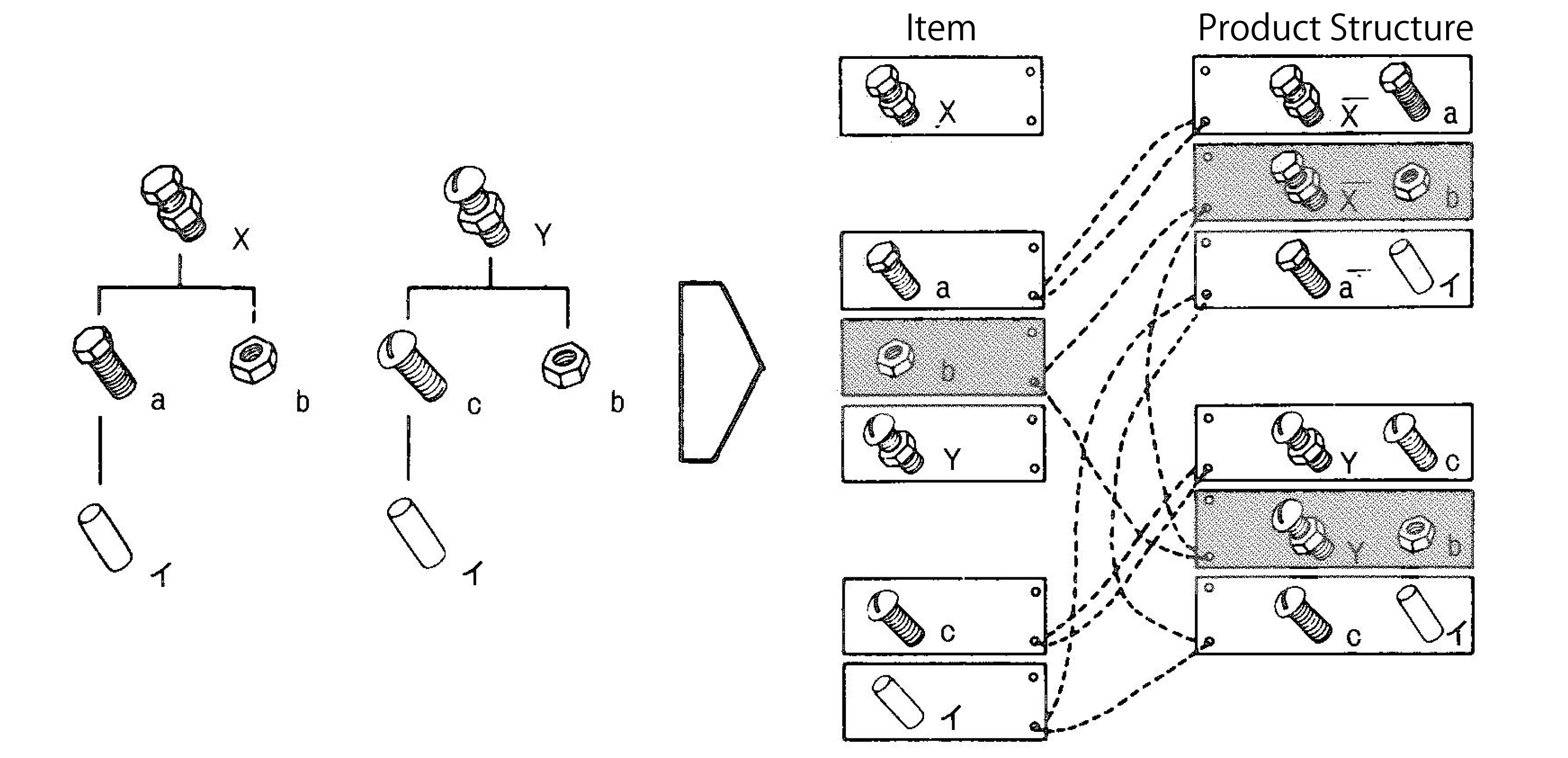 Now parts could be used in various products. How do you discover parts for reuse, and how do you know you have the last released version. For sure their naming cannot be related anymore to a single product or project (a practice still used a lot)
This is where PDM-systems came in. Using additional attributes per file combined with relations between parts, allowing companies to structure and deliver more details related to a part. A detailed description for internal usage, a part type (classification), and the part material were commonly used attributes. And not to forget the status and revision.
 For reuse, it was important that the creators of content had a strategy to define a part for future reuse or discovery. Engineerings were not used to provide such services, filling in data in a PDM-system was seen as an overhead – bureaucracy.
As they were measured on the number of drawings they produced, why do extra work with no immediate benefits?
The best compromise was to have the designer fill in properties in the CAD-file when creating a part. Using the CAD-integration with the PDM-system could be used to fill attributes in the PDM-system.
This “beautiful” simple concept lead later to a lot of complexity.
Is the CAD-model the source of data, meaning designers should always start from CAD when designing a product. If someone added or modified data in the PDM-system, should we open the CAD-file to update some properties? Changing a file means it is a new version. What happens if the CAD-file is released, and I update some connected attributes in PDM?
 To summarize this topic. Companies have missed the opportunity here to implement data governance. However, none of the silos (manufacturing preparation, service) recognized the need. Implementing new tools (3D CAD and PDM) did not affect the company’s way of working.
Instead of people, processes, tools, the only focus was on new tools and satisfying the people withing the same process.
 Of course, when introducing PDM, which happened for mid-market companies at the beginning of this century, there was no PLM vision. Talking about lifecycle support was a waste of time for management. As we will discover in the future posts, large enterprises and small and medium enterprises have the same PLM needs. However, there is already a fundamentally different starting point. Where large enterprises are analyzing and designing business processes, the small and medium enterprises are buying tools to improve the current ways of working
The Future?
 Although we have many steps to take in the upcoming posts, I want to raise your attention to an initiative from the PLM Interest Group together with Xlifecycle.com. The discussion is about what will be PLM’s role in digital transformation.
As you might have noticed, there are people saying the word PLM is no longer covering the right context, and all kinds of alternatives have been suggested. I recommend giving your opinion without my personal guidance. Feel free to answer the questionnaire, and we will be all looking forward to the results.
Find the survey here: Towards a digital future: the evolving role of PLM in the future digital world
Conclusion
We are going slow. Discovering here in this post the split in strategy between large enterprises (process focus) and small and medium enterprises (tool focus) when introducing 3D CAD. This different focus, at this time for PDM, is one of the reasons why vendors are creating functions and features that require methodology solving – however, who will provide the methodology.
Next time more on 3D CAD structures and EBOM

Hi Jos, Knowing your background in methodology and education, I wanted to share a longer article with you: “What is…
Interesting reflection, Jos. In my experience, the situation you describe is very recognizable. At the company where I work, sustainability…
[…] (The following post from PLM Green Global Alliance cofounder Jos Voskuil first appeared in his European PLM-focused blog HERE.) […]
[…] recent discussions in the PLM ecosystem, including PSC Transition Technologies (EcoPLM), CIMPA PLM services (LCA), and the Design for…
Jos, all interesting and relevant. There are additional elements to be mentioned and Ontologies seem to be one of the…