
You are currently browsing the category archive for the ‘CAD data management’ category.
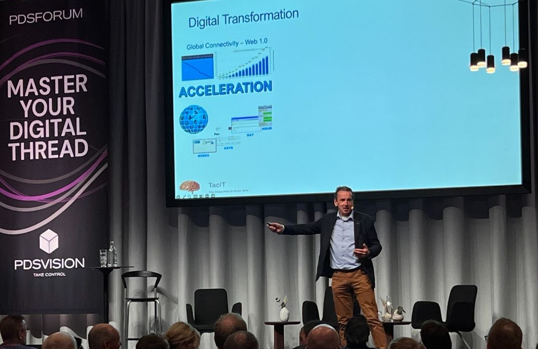
![]() I attended the PDSVISION forum for the first time, a two-day PLM event in Gothenburg organized by PTC’s largest implementer in the Nordics, also active in North America, the UK, and Germany.
I attended the PDSVISION forum for the first time, a two-day PLM event in Gothenburg organized by PTC’s largest implementer in the Nordics, also active in North America, the UK, and Germany.
The theme of the conference: Master your Digital Thread – a hot topic, as it has been discussed in various events, like the recent PLM Roadmap/PDT Europe conference in November 2023.
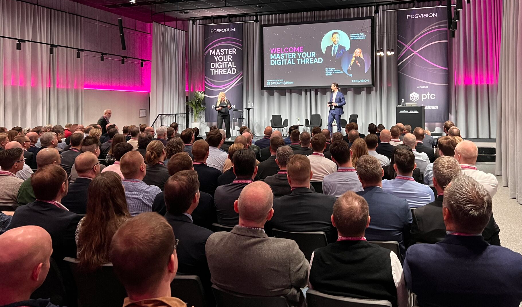
The event drew over 200 attendees, showing the commitment of participants, primarily from the Nordics, to knowledge sharing and learning.
The diverse representation included industry leaders like Vestas, pioneers in Sustainable Energy, and innovative startups like CorPower Ocean, who are dedicated to making wave energy reliable and competitive. Notably, the common thread among these diverse participants was their focus on sustainability, a growing theme in PLM conferences and an essential item on every board’s strategic agenda.
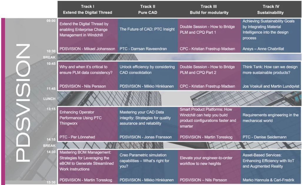
I enjoyed the structure and agenda of the conference. The first day was filled with lectures and inspiring keynotes. The second day was a day of interactive workshops divided into four tracks, which were of decent length so we could really dive into the topics. As you can imagine, I followed the sustainability track.
Here are some of my highlights of this conference.
Catching the Wind: A Digital Thread From Design to Service
 Simon Saandvig Storbjerg, unfortunately remote, gave an overview of the PLM-related challenges that Vestas is addressing. Vestas, the undisputed market leader in wind energy, is indirectly responsible for 231 million tonnes of CO2 per year.
One of the challenges of wind power energy is the growing complexity and need for variants. With continuous innovation and the size of the wind turbine, it is challenging to achieve economic benefits of scale.
As an example, Simon shared data related to the Lost Production Factor, which was around 5% in 2009 and reduced to 2% in 2017 and is now growing again. This trend is valid not only for Vestas but also for all wind turbine manufacturers, as variability is increasing.
Vestas is introducing modularity to address these challenges. I reported last year about their modularity journey related to the North European Modularity biannual meeting held at Vestas in Ringkøbing – you can read the post here.
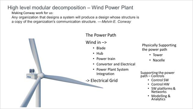
Simon also addressed the importance of Model-Based Definition (MBD), which is crucial if you want to achieve digital continuity between engineering and manufacturing. In particular, in this industry, MBD is a challenge to involve the entire value chain, despite the fact that the benefits are proven and known. Change in people skills and processes remains a challenge.
The Future of Product Design and Development
![]() The session led by PTC from Mark Lobo, General Manager for the PLM Segment, and Brian Thompson, General Manager of the CAD Segment, brought clarity to the audience on the joint roadmap of Windchill and Creo.
The session led by PTC from Mark Lobo, General Manager for the PLM Segment, and Brian Thompson, General Manager of the CAD Segment, brought clarity to the audience on the joint roadmap of Windchill and Creo.
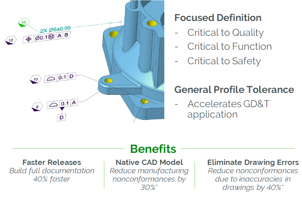 Mark and Brian highlighted the benefits of a Model-Based Enterprise and Model-Based Definition, which are musts if you want to be more efficient in your company and value chain.
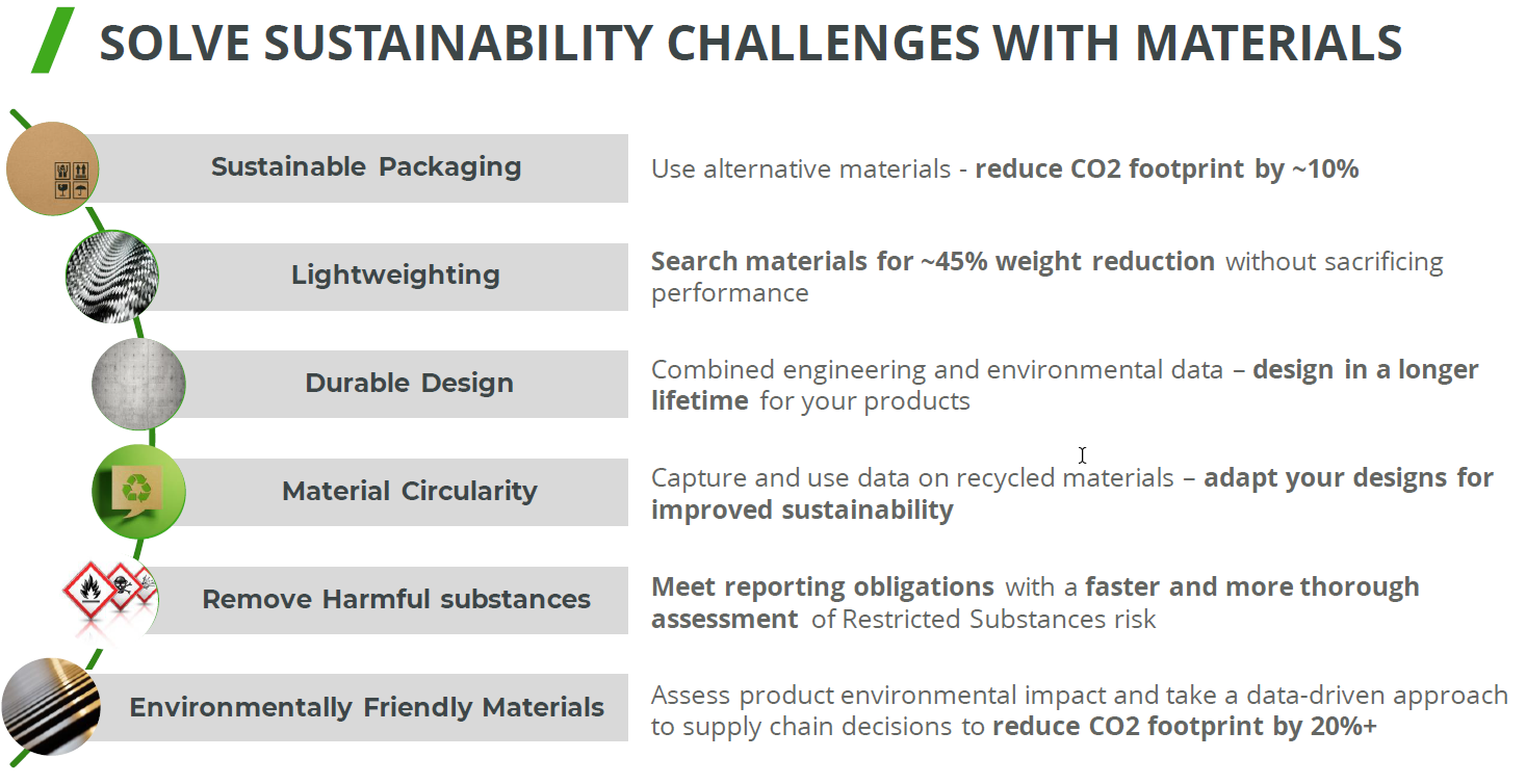
The WHY is known, see the benefits described in the image, and requires new ways of working, something organizations need to implement anyway when aiming to realize a digital thread or digital twin.
In addition, Mark addressed PTC’s focus on Design for Sustainability and their partner network. In relation to materials science, the partnership with Ansys Granta MI is essential. It was presented later by Ansys and discussed on day two during one of the sustainability workshops.
Mark and Brian elaborated on the PTC SaaS journey – the future atlas platform and the current status of WindChill+ and Creo+, addressing a smooth transition from existing customers to a new future architecture.

And, of course, there was the topic of Artificial Intelligence.
 Mark explained that PTC is exploring AI in various areas of the product lifecycle, like validating requirements, optimizing CAD models, streamlining change processes on the design side but also downstream activities like quality and maintenance predictions, improved operations and streamlined field services and service parts are part of the PTC Copilot strategy.
PLM combined with AI is for sure a topic where the applicability and benefits can be high to improve decision-making.
PLM Data Merge in the PTC Cloud: The Why & The How
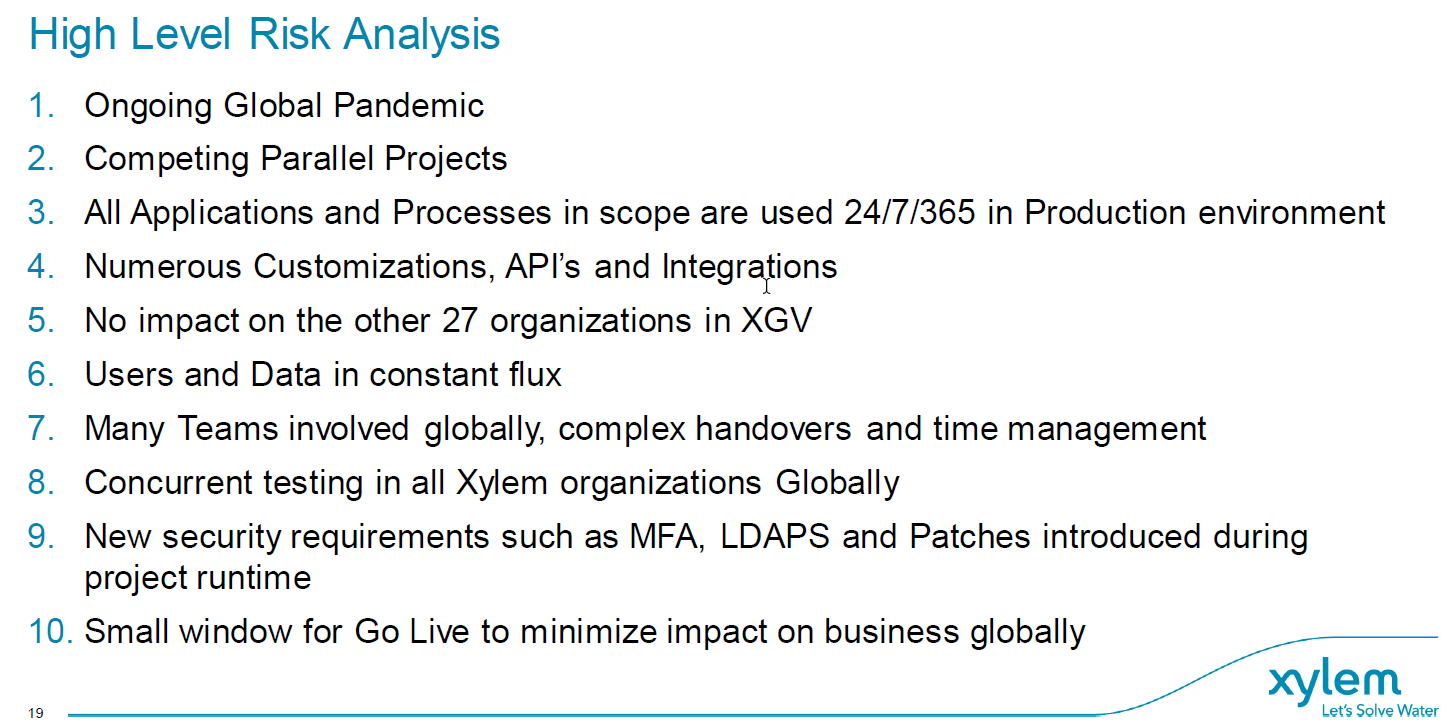
![]() Mikael Gustafson from Xylem, a leading Global Water Solutions provider, described their recently completed project: merging their on-premise Windchill instance TAPIR and their cloud Windchill XGV into a single environment.
Mikael Gustafson from Xylem, a leading Global Water Solutions provider, described their recently completed project: merging their on-premise Windchill instance TAPIR and their cloud Windchill XGV into a single environment.
TAPIR stands for Technical Administration, Part Information Repository and is very much part-centric and used in one organization. XGV stands for Xylem Global Vault, and it is used in 28 organizations with more of a focus on CAD data (Creo and AutoCAD). Two different siloes are to be joined in one instance to build a modern, connected, data-driven future or, as Mikael phrased it: “A step towards a more manageable Virtual Product“.
 It was a severe project involving a lot of resources and time, again showing the challenges of migrations. I am planning to publish a blog post, the draft title “Migration Migraine,” as this type of migration is prevalent in many places because companies want to implement a single PLM backbone beyond (mechanical) engineering.
What I liked about the approach was its focus on assessing the risks and prioritizing a mitigation strategy if necessary. As the list below shows, even the COVID-19 pandemic was challenging the project.
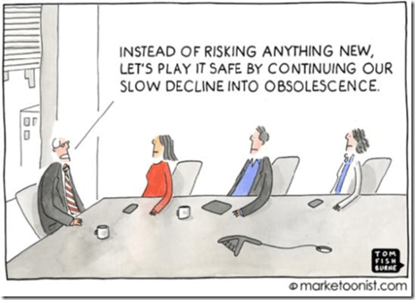
Often, big migration projects fail due to optimism or by assessing some of the risks at the start and then giving it a go.
 When failures happen, there is often the blame game: Was it the software, the implementer, or the customer (past or present) that caused the troubles? Mediating in such environments has been a long time my mission as the “Flying Dutchman,” and from my experience, it is not about the blame game; it is, most of the time, too high expectations and not enough time or resources to fully control this journey.
As Michael said, Xylem was successful, and during the go-live, only a few non-critical issues popped up.
 When asked what he would do differently with the project’s hindsight, Mikael mentioned he would do the migrations not as a big project but as smaller projects.
I can relate a lot to this answer as, by experience, the “one-time” migration projects have created a lot of stress for the company, and only a few of them were successful.
Starting being coordinated and then connected
Several sessions were held where companies shared their PLM journey, to be mapped along the maturity slide (slide 8) I shared in my session: The Why, What and How of Digital Transformation in the PLM domain. You can review the content here on SlideShare.
There was Evolabel, a company starting its PLM journey because they are suffering from ineffective work procedures, information islands and the increasing complexity of its products.
 Evolabel realized it needed PLM to realize its market ambition: To be a market leader within five years. For Evolabel, PLM is a must that is repeatable and integrated internally.
They shared how they first defined the required understanding and mindset for the needed capabilities before implementing them. In my terminology, they started to implement a coordinated PLM approach.
 Teddy Svenson from JBT, a well-known manufacturer of food-tech solutions, described their next step in PLM. From an old AS/400 system with very little integration to PDM to a complete PLM system with parts, configurations, and change management.
It is not an easy task but a vital stepping stone for future development and a complete digital thread, from sales to customer care. In my terminology, they were upgrading their technology to improve their coordinated approach to be ready for the next digital evolution.
![]() There were several other presentations on Day One – See the agenda here I cannot cover them all given the limited size of this blog post.
There were several other presentations on Day One – See the agenda here I cannot cover them all given the limited size of this blog post.
The Workshops
As I followed the Sustainability track, I cannot comment much on the other track; however, given the presenters and the topics, they all appeared to be very pragmatic and interactive – given the format.
Achieving sustainability goals by integrating material intelligence into the design process
![]() In the sustainability track, we started with Manuelle Clavel from Ansys Granta, who explained in detail how material data and its management are crucial for designing better-performing, more sustainable, and compliant products.
In the sustainability track, we started with Manuelle Clavel from Ansys Granta, who explained in detail how material data and its management are crucial for designing better-performing, more sustainable, and compliant products.
With the importance of compliance with (upcoming) regulations and the usage of material characteristics in the context of more sustainable products and being able to perform a Life Cycle Assessment, it is crucial to have material information digitally available, both in the CAD design environment as well in the PLM environment.
For me, a dataset of material properties is an excellent example of how it is used in a connected enterprise. You do not want to copy the information from system to system; it needs to be connected and available in real-time.
How can we design more sustainable products?
Together with Martin Lundqvist from QCM, I conducted an interactive session. We started with the need for digitalization, then looked at RoHS and REACH compliance and discussed the upcoming requirements of the Digital Product Passport.

We closed the session with a dialogue on the circular economy.
From the audience, we learned that many companies are still early in understanding the implementation of sustainability requirements and new processes. However, some were already quite advanced and acting. In particular, it is essential to know if your company is involved with batteries (DPP #1) or is close to consumers.
Conclusion
The PDSFORUM was for me an interesting experience for meeting companies at all different stages of their PLM journey. All sessions I attended were realistic, and the solutions were often pragmatic. In my day-to-day life, inspiring companies to understand a digital and sustainable future, you sometimes forget the journey everyone is going through.
Thanks, PDVISION, for inviting me to speak and learn at this conference.
and some sad news …..

I was sorry to learn that last week, Dr. Ken Versprille suddenly passed away. I know Ken, as shown in the picture – a passionate moderator and timekeeper of the PLM Roadmap / PDT conferences, well prepared for the details. May his spirit live through the future conferences – the next one already on May 8-9th in Washington, DC.
 While preparing my presentation for the Dutch Model-Based Definition solutions event, I had some reflections and experiences discussing Model-Based Definition. Particularly in traditional industries. In the Aerospace & Defense, and Automotive industry, Model-Based Definition has become the standard. However, other industries have big challenges in adopting this approach. In this post, I want to share my observations and bring clarifications about the importance.
What is a Model-Based Definition?
The Wiki-definition for Model-Based Definition is not bad:
 Model-based definition (MBD), sometimes called digital product definition (DPD), is the practice of using 3D models (such as solid models, 3D PMI and associated metadata) within 3D CAD software to define (provide specifications for) individual components and product assemblies. The types of information included are geometric dimensioning and tolerancing (GD&T), component level materials, assembly level bills of materials, engineering configurations, design intent, etc.
By contrast, other methodologies have historically required the accompanying use of 2D engineering drawings to provide such details.
 When I started to write about Model-Based definition in 2016, the concept of a connected enterprise was not discussed. MBD mainly enhanced data sharing between engineering, manufacturing, and suppliers at that time. The 3D PMI is a data package for information exchange between these stakeholders.
The main difference is that the 3D Model is the main information carrier, connected to 2D manufacturing views and other relevant data, all connected in this package.
MBD – the benefits
![]() There is no need to write a blog post related to the benefits of MBD. With some research, you find enough reasons. The most important benefits of MBD are:
There is no need to write a blog post related to the benefits of MBD. With some research, you find enough reasons. The most important benefits of MBD are:
- the information is and human-readable and machine-readable. Allowing the implementation of Smart Manufacturing / Industry 4.0 concepts
- the information relies on processes and data and is no longer dependent on human interpretation. This leads to better quality and error-fixing late in the process.
- MBD information is a building block for the digital enterprise. If you cannot master this concept, forget the benefits of MBSE and Virtual Twins. These concepts don’t run on documents.
To help you discover the benefits of MBD described by others – have a look here:
- What is MBD, and what are its benefits?
- MBD Efficiencies for Small Manufacturers
- 5 reasons to use MBD
- 10 reasons why everyone is moving away from traditional 2D drawings
MBD as a stepping stone to the future
 When you are able to implement model-based definition practices in your organization and connect with your eco-system, you are learning what it means to work in a connected matter. Where the scope is limited, you already discover that working in a connected manner is not the same as mandating everyone to work with the same systems or tools. Instead, it is about new ways of working (skills & people), combined with exchange standards (which to follow).
Where MBD is part of the bigger model-based enterprise, the same principles apply for connecting upstream information (Model-Based Systems Engineering) and downstream information(IoT-based operation and service models).
Oleg Shilovitsky addresses the same need from a data point of view in his recent blog: PLM Strategy For Post COVID Time. He makes an important point about the Digital Thread:
Digital Thread is one of my favorite topics because it is leading directly to the topic of connected data and services in global manufacturing networks.
I agree with that statement as the digital thread is like MBD, another steppingstone to organize information in a connected manner, even beyond the scope of engineering-manufacturing interaction. However, Digital Thread is an intermediate step toward a full data-driven and model-based enterprise.
 To master all these new ways is working, it is crucial for the management of manufacturing companies, both OEM and their suppliers, to initiate learning programs. Not as a Proof of Concept but as a real-life, growing activity.
Why MBD is not yet a common practice?
 If you look at the success of MBD in Aerospace & Defense and Automotive, one of the main reasons was the push from the OEMs to align their suppliers. They even dictated CAD systems and versions to enable smooth and efficient collaboration.
In other industries, there we not so many giant OEMs that could dictate their supply chain. Often also, the OEM was not even ready for MBD. Therefore, the excuse was often we cannot push our suppliers to work different, let’s remain working as best as possible (the old way and some automation)
 Besides the technical changes, MBD also had a business impact. Where the traditional 2D-Drawing was the contractual and leading information carrier, now the annotated 3D Model has to become the contractual agreement. This is much more complex than browsing through (paper) documents; now, you need an application to open up the content and select the right view(s) or datasets.
In the interaction between engineering and manufacturing, you could hear statements like:
you can use the 3D Model for your NC programming, but be aware the 2D drawing is leading. We cannot guarantee consistency between them.
In particular, this is a business change affecting the relationship between an OEM and its suppliers. And we know business changes do not happen overnight.
Smaller suppliers might even refuse to work on a Model-Based definition, as it is considered an extra overhead they do not benefit from.
In particular, when working with various OEMs that might have their own preferred MBD package content based on their preferred usage. There are standards; however, OEMs often push for their preferred proprietary format.
It is about an orchestrated change.
Implementing MBD in your company, like PLM, is challenging because people need to be aligned and trained on new ways of working. In particular, this creates resistance at the end-user level.
 Similar to the introduction of mainstream CAD (AutoCAD in the eighties) and mainstream 3D CAD (Solidworks in the late nineties), it requires new processes, trained people, and matching tools.

I am aware of learning materials coming from the US, not so much about European or Asian thought leaders. Feel free to add other relevant resources for the readers in this post’s comments. Have a look and talk with:
![]() Action Engineering with their OSCAR initiative: Bringing MBD Within Reach. I spoke with Jennifer Herron, founder of Action Engineering, a year ago about MBD and OSCAR in my blog post: PLM and Model-Based Definition.
Action Engineering with their OSCAR initiative: Bringing MBD Within Reach. I spoke with Jennifer Herron, founder of Action Engineering, a year ago about MBD and OSCAR in my blog post: PLM and Model-Based Definition.

Another interesting company to follow is Capvidia. Read their blog post to start with is MBD model-based definition in the 21st century.
The future
What you will discover from these two companies is that they focus on the connected flow of information between companies while anticipating that each stakeholder might have their preferred (traditional) PLM environment. It is about data federation.
 The future of a connected enterprise is even more complex. So I was excited to see and download Yousef Hooshmand’s paper: ”From a Monolithic PLM Landscape to a Federated Domain and Data Mesh”.
Yousef and some of his colleagues report about their PLM modernization project @Mercedes-Benz AG, aiming at transforming a monolithic PLM landscape into a federated Domain and Data Mesh.
This paper provides a lot of structured thinking related to the concepts I try to explain to my audience in everyday language. See my The road to model-based and connected PLM thoughts.
This paper has much more depth and is a must-read and must-discuss writing for those interested – perhaps an opportunity for new startups and a threat to traditional PLM vendors.
Conclusion
Vellum drawings are almost gone now – we have electronic 2D Drawings. The model-based definition has confirmed the benefits of improving the interaction between engineering, manufacturing & suppliers. Still, many industries are struggling with this approach due to process & people changes needed. If you are not able or willing to implement a model-based definition approach, be worried about the future. The eco-systems will only run efficiently (and survive) when their information exchange is based on data and models. Start learning now.
p.s. just out of curiosity:
If you are model-based advocate support this post with a 
 In my last post in this series, The road to model-based and connected PLM, I mentioned that perhaps it is time to talk about SLM instead of PLM when discussing popular TLA’s for our domain of expertise. There were not so many encouraging statements for SLM so far.
SLM could mean for me, Solution Lifecycle Management, considering that the company’s offering more and more is a mix of products and services. Or SLM could mean System Lifecycle Management, in that case pushing the idea that more and more products are interacting with the outside world and therefore could be considered systems. Products are (almost) dead.
In addition, I mentioned that the typical product lifecycle and related configuration management concepts need to change as in the SLM domain. There is hardware and software with different lifecycles and change processes.
 It is a topic I want to explore further. I am curious to learn more from Martijn Dullaart, who will be lecturing at the PLM Road map and PDT 2021 fall conference in November. I hope my expectations are not too high, knowing it is a topic of interest for Martijn. Feel free to join this discussion
In this post, it is time to follow up on my third statement related to what data-driven implies:
Data-driven means that we need to manage data in a much more granular manner. We have to look different at data ownership. It becomes more about data accountability per role as the data can be used and consumed throughout the product lifecycle
On this topic, I have a list of points to consider; let’s go through them.
The dataset
In this post, I will often use the term dataset (you are also allowed to write the data set I understood).
 A dataset means a predefined number of attributes and values that belong logically to each other. Datasets should be defined based on the purpose and, if possible, designated for a single goal. In this way, they can be stored in a database.
Combined with other datasets, a combination can result in relevant business information. Note a dataset is not only transactional data; a dataset could also describe geometry.
Identify the dataset
 In the document-based world, a lot of information could be stored in a single file. In a data-driven world, we should define a dataset that contains a specific piece of information, logically belonging together. If we are more precise, a part would have various related datasets that make up the definition of a part. These definitions could be:
- Core identification attributes like ID, Name, Type and Status
- The Type could define a set of linked information. For example, a valve would have different characteristics as a resistor. Through classification, we can link data sets to the core definition of a part.
- The part can have engineering-specific data (CAD and metadata), manufacturing-specific data, supplier-specific data, and service-specific data. Each of these datasets needs to be defined as a unique element in a data-driven environment
- CAD is a particular case as most current CAD systems don’t treat geometry as a single dataset. In a file-based world, many other datasets are stored in the file (e.g., engineering or manufacturing details). In a data-driven environment, we want to have the CAD definition to be treated like a dataset. Dassault Systèmes with their CATIA V6 and 3DEXPERIENCE platform or PTC with OnShape are examples of this approach.Having CAD as separate datasets makes sharing and collaboration so much easier, as we can see from these solutions. The concept for CAD stored in a database is not new, and this approach has been used in various disciplines. Mechanical CAD was always a challenge.
![]() Thanks to Moore’s Law (approximate every 2 years, processor power doubled – click on the image for the details) and higher network connection speed, it starts to make sense to have mechanical CAD also stored in a database instead of a file
Thanks to Moore’s Law (approximate every 2 years, processor power doubled – click on the image for the details) and higher network connection speed, it starts to make sense to have mechanical CAD also stored in a database instead of a file
An important point to consider is a kind of standardization of datasets. In theory, there should be a kind of minimum agreed collection of datasets. Industry standards provide these collections in their dictionary. Whenever you optimize your data model for a connected enterprise, make sure you look first into the standards that apply to your industry.
 They might not be perfect or complete, but inventing your own new standard is a guarantee for legacy issues in the future. This remark is also valid for the software vendors in this domain. A proprietary data model might give you a competitive advantage.
Still, in the long term, there is always the need to connect with outside stakeholders.
Identify the RACI
To ensure a dataset is complete and well maintained, the concept of RACI could be used. RACI is the abbreviation for Responsible Accountable Consulted and Informed and a simplification of the RASCI Model, see also a responsibility assignment matrix.
 In a data-driven environment, there is no data ownership anymore like you have for documents. The main reason that data ownership can no longer be used is that datasets can be consumed by anyone in the ecosystem. No longer only your department or the manufacturing or service department.
Data sets in a data-driven environment bring value when connected with other datasets in applications or dashboards.
A dataset describing the specification attributes of a part could be used in a spare part app and a service app. Of course, the dataset will be used in a different context – still, we need to ensure we can trust the data.
Therefore, per identified dataset, there should be governed by a kind of RACI concept. The RACI concept is a way to break the siloes in an organization.
Identify Inside / outside
There is a lot of fear that a connected, data-driven environment will expose Intellectual Property (IP). It came up in recent discussions. If you like storytelling and technology, read my old SmarTeam colleague Alex Bruskin’s post: The Bilbo Baggins Threat to PLM Assets. Alex has written some “poetry” with a deep technical message behind it.
 It is true that if your data set is too big, you have the challenge of exposing IP when connecting this dataset with others. Therefore, when building a data model, you should make it possible to have datasets pure for internal usage and datasets for sharing.
When you use the concept of RACI, the difference should be defined by the I(informed) – is it PLM-data or PIM-data for example?
Tracking relations
Suppose we follow up on the concept of datasets. In that case, it becomes clear that relations between the datasets are as crucial as the dataset. In traditional PLM applications, these relations are often predefined as part of the core data model/
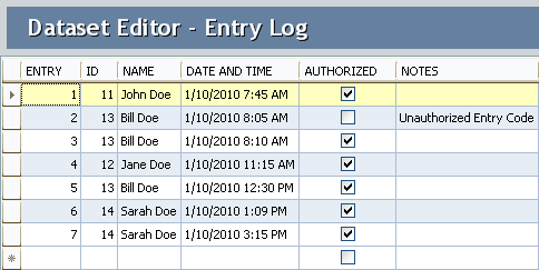
 For example, the EBOM parts have relationships between themselves and specification data – see image.
The MBOM parts have links with the supplier data or the manufacturing process.
The prepared relations in a PLM system allow people to implement the system relatively quickly to map their approaches to this taxonomy.
 However, traditional PLM systems are based on a document-based (or file-based) taxonomy combined with related metadata. In a model-based and connected environment, we have to get rid of the document-based type of data.
Therefore, the datasets will be more granular, and there is a need to manage exponential more relations between datasets.
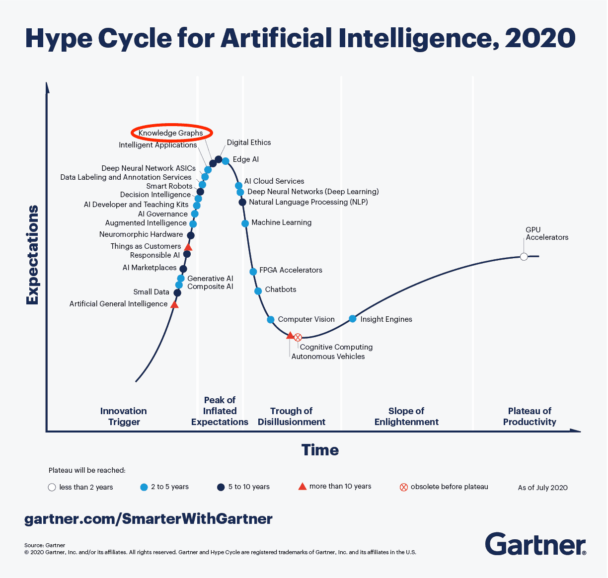 This is why you see the graph database coming up as a needed infrastructure for modern connected applications. If you haven’t heard of a graph database yet, you are probably far from technology hypes. To understand the principles of a graph database you can read this article from neo4j: Graph Databases for Beginners: Why graph technology is the future
As you can see from the 2020 Gartner Hype Cycle for Artificial Intelligence this technology is at the top of the hype and conceptually the way to manage a connected enterprise. The discussion in this post also demonstrates that besides technology there is a lot of additional conceptual thinking needed before it can be implemented.
Although software vendors might handle the relations and datasets within their platform, the ultimate challenge will be sharing datasets with other platforms to get a connected ecosystem.
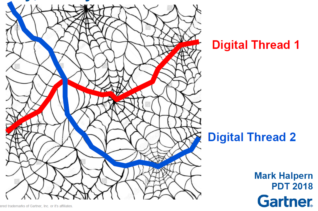
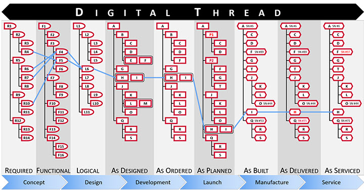
For example, the digital web picture shown above and introduced by Marc Halpern at the 2018 PDT conference shows this concept. Recently CIMdata discussed this topic in a similar manner: The Digital Thread is Really a Web, with the Engineering Bill of Materials at Its Center
(Note I am not sure if CIMdata has published a recording of this webinar – if so I will update the link)
Anyway, these are signs that we started to find the right visuals to imagine new concepts. The traditional digital thread pictures, like the one below, are, for me, impressions of the past as they are too rigid and focusing on some particular value streams.
From a distance, it looks like a connected enterprise should work like our brain. We story information on different abstraction levels. We keep incredibly many relations between information elements. As the brain is a biological organ, connections degrade or get lost. Or the opposite other relationships become so strong that we cannot change them anymore. (“I know I am always right”)
 Interestingly, the brain does not use the “single source of truth”-concept – there can be various “truths” inside a brain. This makes us human beings with all the good and the harmful effects of that.
As long as we realize there is no single source of truth.
In business and our technological world, we need sometimes the undisputed truth. Blockchain could be the basis for securing the right connections between datasets to guarantee the result is valid. I am curious if blockchain can scale to complex connected situations, although Moore’s Law might ultimately help us here too(if still valid).
 The topic is not new – in 2014 I wrote a post with the title: PLM is doomed unless …. Where I introduced the topic of owning and sharing in the context of the human brain. In the post, I refer to the book On Intelligence by Jeff Hawkins how tries to analyze what is human-based intelligence and how could we apply it to our technology concepts. Still a fascinating book worth reading if you have the time and opportunity.
Conclusion
A data-driven approach requires a more granular definition of information, leading to the concepts of datasets and managing relations between datasets. This is a fundamental difference compared to the past, where we were operating systems with information. Now we are heading towards connected platforms that provide a filtered set of real-time data to act upon.
I am curious to learn more about how people have solved the connected challenges and in what kind of granularity. Let us know!
After the first article discussing “The Future of PLM,” now again a post in the category of PLM and complementary practices/domains a topic that is already for a long time on the radar: Model-Based Definition, I am glad to catch up with Jennifer Herron, founder of Action Engineering, who is one of the thought leaders related to Model-Based Definition (MBD) and Model-Based Enterprise (MBE).

In 2016 I spoke with Jennifer after reading her book: “Re-Use Your CAD – The Model-Based CAD Handbook”. At that time, the discussion was initiated through two articles on Engineering.com. Action Engineering introduced OSCAR seven years later as the next step towards learning and understanding the benefits of Model-Based Definition.
Therefore, it is a perfect moment to catch up with Jennifer. Let’s start.
Model-Based Definition
 Jennifer, first of all, can you bring some clarity in terminology. When I discussed the various model-based approaches, the first response I got was that model-based is all about 3D Models and that a lot of the TLA’s are just marketing terminology.
Can you clarify which parts of the model-based enterprise you focus on and with the proper TLA’s?
 Model-Based means many things to many different viewpoints and systems of interest. All these perspectives lead us down many rabbit holes, and we are often left confused when first exposed to the big concepts of model-based.
At Action Engineering, we focus on Model-Based Definition (MBD), which uses and re-uses 3D data (CAD models) in design, fabrication, and inspection.
There are other model-based approaches, and the use of the word “model” is always a challenge to define within the proper context.
For MBD, a model is 3D CAD data that comes in both native and neutral formats

Another model-based approach is Model-Based Systems Engineering (MBSE). The term “model” in this context is a formalized application of modeling to support system requirements, design, analysis, verification and validation activities beginning in the conceptual design phase and continuing throughout development and later lifecycle phases.
<Jos> I will come back on Model-Based Systems Engineering in future posts
Sometimes MBSE is about designing widgets, and often it is about representing the entire system and the business operations. For MBD, we often focus our education on the ASME Y14.47 definition that MBD is an annotated model and associated data elements that define the product without a drawing.
Model-Based Definition for Everybody?
I believe it took many years till 3D CAD design became a commodity; however, I still see the disconnected 2D drawing used to specify a product or part for manufacturing or suppliers. What are the benefits of model-based definition?
Are there companies that will not benefit from the model-based definition?
There’s no question that the manufacturing industry is addicted to their drawings. There are many reasons why, and yet mostly the problem is lack of awareness of how 3D CAD data can make design, fabrication, and inspection work easier.
 For most, the person doing an inspection in the shipping and receiving department doesn’t have exposure to 3D data, and the only thing they have is a tabulated ERP database and maybe a drawing to read. If you plop down a 3D viewable that they can spin and zoom, they may not know how that relates to their job or what you want them to do differently.
Today’s approach of engineering championing MBD alone doesn’t work. To evolve information from the 2D drawing onto the 3D CAD model without engaging the stakeholders (machinists, assembly technicians, and inspectors) never yields a return on investment.
Organizations that succeed in transitioning to MBD are considering and incorporating all departments that touch the drawing today.
Incorporating all departments requires a vision from the management. Can you give some examples of companies that have transitioned to MBD, and what were the benefits they noticed?
I’ll give you an example of a small company with no First Article Inspection (FAI) regulatory requirements and a huge company with very rigorous FAI requirements.
Note: click on the images below to enjoy the details.
 The small company instituted a system of CAD modeling discipline that allowed them to push 3D viewable information directly to the factory floor. The assembly technicians instantly understood engineering’s requirements faster and better.
The positive MBD messages for these use cases are 3D navigation, CAD Re-Use, and better control of their revisions on the factory floor.
 The large company has added inspection requirements directly onto their engineering and created a Bill of Characteristics (BOC) for the suppliers and internal manufacturers. They are removing engineering ambiguity, resulting in direct digital information exchange between engineering, manufacturing, and quality siloes.
These practices have reduced error and reduced time to market.
The positive MBD messages for these use cases are unambiguous requirements capture by Engineering, Quality Traceability, and Model-Based PMI (Product and Manufacturing Information).
Model-Based Definition and PLM?
How do you see the relation between Model-Based Definition and PLM? Is a PLM system a complication or aid to implement a Model-Based Definition? And do you see a difference between the old and new PLM Vendors?
Model-Based Definition data is complex and rich in connected information, and we want it to be. With that amount of connected data, a data management system (beyond upload/download of documents) must keep all that data straight.
Depending on the size and function of an organization, a PLM may not be needed. However, a way to manage changes and collaboration amongst those using 3D data is necessary. Sometimes that results in a less sophisticated Product Data Management (PDM) system. Large organizations often require PLM.
 There is significant resistance to doing MBD and PLM implementations simultaneously because PLM is always over budget and behind schedule. However, doing just MBD or just PLM without the other doesn’t work either. I think you should be brave and do both at once.
I think we can debate why PLM is always over budget and behind schedule. I hear the same about ERP implementations. Perhaps it has to deal with the fact that enterprise applications have to satisfy many users?
I believe that working with model versions and file versions can get mixed in larger organizations, so there is a need for PDM or PLM. Have you seen successful implementations of both interacting together?
Yes, the only successful MBD implementations are those that already have a matured PDM/PLM (scaled best to the individual business).
Model-Based Definition and Digital Transformation
In the previous question, we already touched on the challenge of old and modern PLM. How do you see the introduction of Model-Based Definition addressing the dreams of Industry 4.0, the Digital Twin and other digital concepts?
I just gave a presentation at the ASME Digital Twin Summit discussing the importance of MBD for the Digital Twin. MBD is a foundational element that allows engineering to compare their design requirements to the quality inspection results of digital twin data.
The feedback loop between Engineering and Quality is fraught with labor-intensive efforts in most businesses today.
Leveraging the combination of MBD and Digital Twin allows automation possibilities to speed up and increase the accuracy of the engineering to inspection feedback loop. That capability helps organizations realize the vision of Industry 4.0.
And then there is OSCAR.
I noticed you announced OSCAR. First, I thought OSCAR was a virtual aid for model-based definition, and I liked the launching page HERE. Can you tell us more about what makes OSCAR unique?
One thing that is hard with MBD implementation is there is so much to know. Our MBDers at Action Engineering have been involved with MBD for many years and with many companies. We are embedded in real-life transitions from using drawings to using models.
Suppose you start down the model-based path for digital manufacturing. In that case, there are significant investments in time to learn how to get to the right set of capabilities and the right implementation plan guided by a strategic focus. OSCAR reduces that ramp-up time with educational resources and provides vetted and repeatable methods for an MBD implementation.
![]() OSCAR combines decades of Action Engineering expertise and lessons learned into a multi-media textbook of sorts. To kickstart an individual or an organization’s MBD journey, it includes asynchronous learning, downloadable resources, and CAD examples available in Creo, NX, and SOLIDWORKS formats.
OSCAR combines decades of Action Engineering expertise and lessons learned into a multi-media textbook of sorts. To kickstart an individual or an organization’s MBD journey, it includes asynchronous learning, downloadable resources, and CAD examples available in Creo, NX, and SOLIDWORKS formats.
CAD users can access how-to training and downloadable resources such as the latest edition of Re-Use Your CAD (RUYC). OSCAR enables process improvement champions to make their case to start the MBD journey. We add content regularly and post what’s new. Free trials are available to check out the online platform.
Learn more about what OSCAR is here:
Want to learn more?
In this post, I believe we only touched the tip of the iceberg. There is so much to learn and understand. What would you recommend to a reader of this blog who got interested?
RUYC (Re-Use Your CAD) is an excellent place to start, but if you need more audio-visual, and want to see real-life examples of MBD in action, get a Training subscription of OSCAR to get rooted in the vocabulary and benefits of MBD with a Model-Based Enterprise. Watch the videos multiple times! That’s what they are for. We love to work with European companies and would love to support you with a kickstart coaching package to get started.
What I learned
First of all, I learned that Jennifer is a very pragmatic person. Her company (Action Engineering) and her experience are a perfect pivot point for those who want to learn and understand more about Model-Based Definition. In particular, in the US, given her strong involvement in the American Society of Mechanical Engineers (ASME).
I am still curious if European or Asian counterparts exist to introduce and explain the benefits and usage of Model-Based Definition to their customers. Feel free to comment.
Next, and an important observation too, is the fact that Jennifer also describes the tension between Model-Based Definition and PLM. Current PLM systems might be too rigid to support end-to-end scenarios, taking benefit of the Model-Based definition.
 I have to agree here. PLM Vendors mainly support their own MBD (model-based definition), where the ultimate purpose is to share all product-related information using various models as the main information carriers efficiently.
We have to study and solve a topic in the PLM domain, as I described in my technical highlights from the PLM Road Map & PDT Spring 2021 conference.
There is work to do!
Conclusion
Model-Based Definition is, for me, one of the must-do steps of a company to understand the model-based future. A model-based future sometimes incorporates Model-Based Systems Engineering, a real Digital Thread and one or more Digital Twins (depending on your company’s products).
It is a must-do activity because companies must transform themselves to depend on digital processes and digital continuity of data to remain competitive. Document-driven processes relying on the interpretation of a person are not sustainable.
After the first article discussing “The Future of PLM,” now again a post in the category of PLM and complementary practices/domains a topic that is already for a long time on the radar: Model-Based Definition, I am glad to catch up with Jennifer Herron, founder of Action Engineering, who is one of the thought leaders related to Model-Based Definition (MBD) and Model-Based Enterprise (MBE).
In 2016 I spoke with Jennifer after reading her book: “Re-Use Your CAD – The Model-Based CAD Handbook”. At that time, the discussion was initiated through two articles on Engineering.com. Action Engineering introduced OSCAR seven years later as the next step towards learning and understanding the benefits of Model-Based Definition.
Therefore, it is a perfect moment to catch up with Jennifer. Let’s start.
Model-Based Definition
Jennifer, first of all, can you bring some clarity in terminology. When I discussed the various model-based approaches, the first response I got was that model-based is all about 3D Models and that a lot of the TLA’s are just marketing terminology.
Can you clarify which parts of the model-based enterprise you focus on and with the proper TLA’s?
Model-Based means many things to many different viewpoints and systems of interest. All these perspectives lead us down many rabbit holes, and we are often left confused when first exposed to the big concepts of model-based.
At Action Engineering, we focus on Model-Based Definition (MBD), which uses and re-uses 3D data (CAD models) in design, fabrication, and inspection.
There are other model-based approaches, and the use of the word “model” is always a challenge to define within the proper context.
For MBD, a model is 3D CAD data that comes in both native and neutral formats
Another model-based approach is Model-Based Systems Engineering (MBSE). The term “model” in this context is a formalized application of modeling to support system requirements, design, analysis, verification and validation activities beginning in the conceptual design phase and continuing throughout development and later lifecycle phases.
<Jos> I will come back on Model-Based Systems Engineering in future posts
Sometimes MBSE is about designing widgets, and often it is about representing the entire system and the business operations. For MBD, we often focus our education on the ASME Y14.47 definition that MBD is an annotated model and associated data elements that define the product without a drawing.
Model-Based Definition for Everybody?
I believe it took many years till 3D CAD design became a commodity; however, I still see the disconnected 2D drawing used to specify a product or part for manufacturing or suppliers. What are the benefits of model-based definition?
Are there companies that will not benefit from the model-based definition?
There’s no question that the manufacturing industry is addicted to their drawings. There are many reasons why, and yet mostly the problem is lack of awareness of how 3D CAD data can make design, fabrication, and inspection work easier.
For most, the person doing an inspection in the shipping and receiving department doesn’t have exposure to 3D data, and the only thing they have is a tabulated ERP database and maybe a drawing to read. If you plop down a 3D viewable that they can spin and zoom, they may not know how that relates to their job or what you want them to do differently.
Today’s approach of engineering championing MBD alone doesn’t work. To evolve information from the 2D drawing onto the 3D CAD model without engaging the stakeholders (machinists, assembly technicians, and inspectors) never yields a return on investment.
Organizations that succeed in transitioning to MBD are considering and incorporating all departments that touch the drawing today.
Incorporating all departments requires a vision from the management. Can you give some examples of companies that have transitioned to MBD, and what were the benefits they noticed?
I’ll give you an example of a small company with no First Article Inspection (FAI) regulatory requirements and a huge company with very rigorous FAI requirements.
Note: click on the images below to enjoy the details.
The small company instituted a system of CAD modeling discipline that allowed them to push 3D viewable information directly to the factory floor. The assembly technicians instantly understood engineering’s requirements faster and better.
The positive MBD messages for these use cases are 3D navigation, CAD Re-Use, and better control of their revisions on the factory floor.
The large company has added inspection requirements directly onto their engineering and created a Bill of Characteristics (BOC) for the suppliers and internal manufacturers. They are removing engineering ambiguity, resulting in direct digital information exchange between engineering, manufacturing, and quality siloes.
These practices have reduced error and reduced time to market.
The positive MBD messages for these use cases are unambiguous requirements capture by Engineering, Quality Traceability, and Model-Based PMI (Product and Manufacturing Information).
Model-Based Definition and PLM?
How do you see the relation between Model-Based Definition and PLM? Is a PLM system a complication or aid to implement a Model-Based Definition? And do you see a difference between the old and new PLM Vendors?
Model-Based Definition data is complex and rich in connected information, and we want it to be. With that amount of connected data, a data management system (beyond upload/download of documents) must keep all that data straight.
Depending on the size and function of an organization, a PLM may not be needed. However, a way to manage changes and collaboration amongst those using 3D data is necessary. Sometimes that results in a less sophisticated Product Data Management (PDM) system. Large organizations often require PLM.
There is significant resistance to doing MBD and PLM implementations simultaneously because PLM is always over budget and behind schedule. However, doing just MBD or just PLM without the other doesn’t work either. I think you should be brave and do both at once.
I think we can debate why PLM is always over budget and behind schedule. I hear the same about ERP implementations. Perhaps it has to deal with the fact that enterprise applications have to satisfy many users?
I believe that working with model versions and file versions can get mixed in larger organizations, so there is a need for PDM or PLM. Have you seen successful implementations of both interacting together?
Yes, the only successful MBD implementations are those that already have a matured PDM/PLM (scaled best to the individual business).
Model-Based Definition and Digital Transformation
In the previous question, we already touched on the challenge of old and modern PLM. How do you see the introduction of Model-Based Definition addressing the dreams of Industry 4.0, the Digital Twin and other digital concepts?
I just gave a presentation at the ASME Digital Twin Summit discussing the importance of MBD for the Digital Twin. MBD is a foundational element that allows engineering to compare their design requirements to the quality inspection results of digital twin data.
The feedback loop between Engineering and Quality is fraught with labor-intensive efforts in most businesses today.
Leveraging the combination of MBD and Digital Twin allows automation possibilities to speed up and increase the accuracy of the engineering to inspection feedback loop. That capability helps organizations realize the vision of Industry 4.0.
And then there is OSCAR.
I noticed you announced OSCAR. First, I thought OSCAR was a virtual aid for model-based definition, and I liked the launching page HERE. Can you tell us more about what makes OSCAR unique?
One thing that is hard with MBD implementation is there is so much to know. Our MBDers at Action Engineering have been involved with MBD for many years and with many companies. We are embedded in real-life transitions from using drawings to using models.
Suppose you start down the model-based path for digital manufacturing. In that case, there are significant investments in time to learn how to get to the right set of capabilities and the right implementation plan guided by a strategic focus. OSCAR reduces that ramp-up time with educational resources and provides vetted and repeatable methods for an MBD implementation.
![]() OSCAR combines decades of Action Engineering expertise and lessons learned into a multi-media textbook of sorts. To kickstart an individual or an organization’s MBD journey, it includes asynchronous learning, downloadable resources, and CAD examples available in Creo, NX, and SOLIDWORKS formats.
OSCAR combines decades of Action Engineering expertise and lessons learned into a multi-media textbook of sorts. To kickstart an individual or an organization’s MBD journey, it includes asynchronous learning, downloadable resources, and CAD examples available in Creo, NX, and SOLIDWORKS formats.
CAD users can access how-to training and downloadable resources such as the latest edition of Re-Use Your CAD (RUYC). OSCAR enables process improvement champions to make their case to start the MBD journey. We add content regularly and post what’s new. Free trials are available to check out the online platform.
Learn more about what OSCAR is here:
Want to learn more?
In this post, I believe we only touched the tip of the iceberg. There is so much to learn and understand. What would you recommend to a reader of this blog who got interested?
RUYC (Re-Use Your CAD) is an excellent place to start, but if you need more audio-visual, and want to see real-life examples of MBD in action, get a Training subscription of OSCAR to get rooted in the vocabulary and benefits of MBD with a Model-Based Enterprise. Watch the videos multiple times! That’s what they are for. We love to work with European companies and would love to support you with a kickstart coaching package to get started.
What I learned
First of all, I learned that Jennifer is a very pragmatic person. Her company (Action Engineering) and her experience are a perfect pivot point for those who want to learn and understand more about Model-Based Definition. In particular, in the US, given her strong involvement in the American Society of Mechanical Engineers (ASME).
I am still curious if European or Asian counterparts exist to introduce and explain the benefits and usage of Model-Based Definition to their customers. Feel free to comment.
Next, and an important observation too, is the fact that Jennifer also describes the tension between Model-Based Definition and PLM. Current PLM systems might be too rigid to support end-to-end scenarios, taking benefit of the Model-Based definition.
I have to agree here. PLM Vendors mainly support their own MBD (model-based definition), where the ultimate purpose is to share all product-related information using various models as the main information carriers efficiently.
We have to study and solve a topic in the PLM domain, as I described in my technical highlights from the PLM Road Map & PDT Spring 2021 conference.
There is work to do!
Conclusion
Model-Based Definition is, for me, one of the must-do steps of a company to understand the model-based future. A model-based future sometimes incorporates Model-Based Systems Engineering, a real Digital Thread and one or more Digital Twins (depending on your company’s products).
It is a must-do activity because companies must transform themselves to depend on digital processes and digital continuity of data to remain competitive. Document-driven processes relying on the interpretation of a person are not sustainable.
 Last time in the series Learning from the past to understand the future, we zoomed in on how the 3D CAD-structure in the mid-market had to evolve. In a typical Engineering To Order (ETO) scenario, it makes sense to extract from the 3D CAD-structure a BOM-structure to collect all the individual parts that are needed for manufacturing. Combined with the drawings generated based on the 3D CAD assemblies/parts, the complete manufacturing information could be provided. Let’s have a look.
The BOM in ERP (part 1)
To understand what most mid-market companies have been doing, I created the image below. When you click on it, you will have an enlarged version.
Note: for educational purposes an extremely simplified example
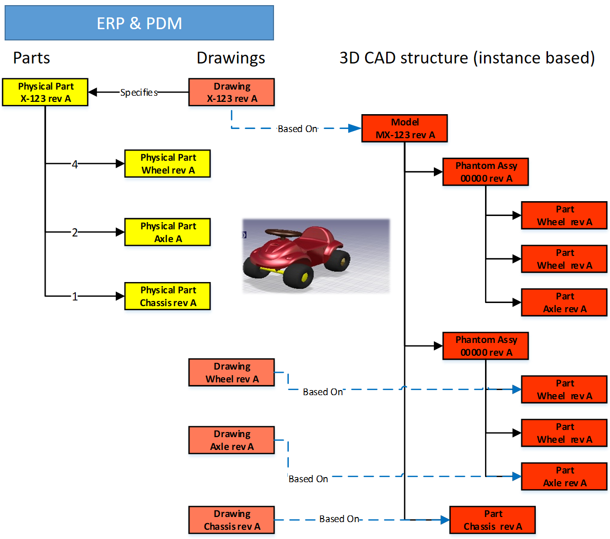
There is a lot to explain here.
First, on the right we see the 3D CAD assembly, two phantom assemblies, grouping the wheels and the axle. And at the end, the individual parts, i.e. chassis, axle, and wheel. The 3D CAD-structure is an instance-based structure; therefore, there are no quantities in the structure (all quantity 1)
For the individual parts, there are drawings. Also, for the product, we have an assembly drawing. The drawings are essential as we want to have them in the ERP-system for manufacturing.
Finally, the physical parts, now with a different ID than the drawing as we learned this one-to-one relation created a lot of extra work. The physical parts are often called Items or Materials (SAP naming). Unfortunately, for engineering, there is a different meaning behind Materials. Still, SAP’s data model was not built with an engineering mindset.
The physical part structure, which we call the BOM contains quantities. Most PDM-CAD-integrations can filter out phantom assemblies and summarize the parts on the same level
 I am still reluctant to call the Part-structure an EBOM as the design of the product has been mainly focusing on extracting manufacturing information, parts, and drawings.
The BOM in ERP (part 2)
In customized PDM-implementations, some implementers created an interface from the BOM-structure to ERP, so the ERP-system would have the basic definition of the parts and a copy of the relevant drawings.
Now manufacturing could create the manufacturing definition without the need to go into the PDM-system.
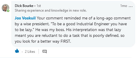
Some “clever” – Dick Bourke would say “smart – therefore lazy” – proposed to “draw” also manufacturing entities in the 3D CAD-structure, so the PDM-CAD-interface would automatically deliver manufacturing parts too inside the ERP. In the example below, we added paint for the body and grease needed for the axels.
Although “smart, a new problem was introduced here – the 3D CAD-structure, instance-based, always has quantities 1. The extracted BOM would have rounded numbers when considering design parts. Now the grease comes with an estimate of 0.025 kg, assuming quantities are based on SI-units. We could also add other manufacturing information to this BOM, like 0.3-liter paint. Anyway, the result would look like below:
Important to notice from the diagram here: There are placeholders for grease and paint “drawn” in the 3D CAD-structure – parts without a geometrical definition and, therefore, not having an associated drawing. However, these parts have a material specification, and therefore in the BOM-structure, they appear as Materials.
Next in the BOM-structure, the engineers would enter the expected/required quantity – which is no longer a rounded number.
 At this stage, you cannot call the BOM on the left an EBOM. It is a kind of hybrid structure, combining engineering and manufacturing data. A type of BOM we discover a lot in companies that started with a type of ETO-product.
The ETO-product
 Many companies that developed specialized machinery have started with a base product, from where they developed the custom solution – their IP. Next, with more and more customers, the original solution was extended by creating either new or changed capabilities.
I worked a lot with companies that moved to the full definition of their products in 3D CAD, creating a correct 3D CAD-structure per customer order. Instead of creating new BOM variants, companies were often tempted/forced to make the configuration inside the 3D CAD-model.

Every time one of the configurations of the part would change, or a new configuration was added, the file has to be revised.
 And if the change was at level five of a 3D CAD-structure, many assembly files needed to be updated. The versioning problem illustrates the challenge of managing configurations inside a 3D CAD-file, meanwhile creating complexity for the PDM/PLM-system.
Last week Tech-Clarity published the highlights of their survey: Bringing Custom-Engineered Products to Market with a link to the full report, sponsored by Propel.
 As you can imagine, this survey is more about PLM collaboration, breaking down the silos and acting agile. Unfortunately, the report does not expose required methodologies, like modularity and “common sense” engineering practices that we discuss here. Still worthwhile to read as the report addresses precisely the type of companies I am referring too here.
If we look at the methodology of custom-engineered products, let us look at how their “best practice” from the past is blocking the future.
When a new customer request is coming in, sales engineering is looking for the best match of delivered products. Hopefully, 80-90 % remains the same, and engineering has to focus only on the differences.
 First, the best-match 3D CAD-structure is copied to a new project. As you can see most 3D CAD-systems provide the functionality to create a derived structure from an original 3D CAD-structure. From there, a traditional ETO-process starts as described at the beginning of this post. We complete the 3D CAD-structure with manufacturing in mind, generate the BOM and drawings, and we can deliver. In the case of purchase parts, the generated BOM often contains already the supplier part number in the 3D CAD-structure as we are focusing on this single delivery.
The disadvantage of this approach that in theory, we have to check if the structure that we reused is really the best so far, otherwise we introduce errors again.
 The second disadvantage is that if one supplier part in the structure becomes obsolete and needs to be revised, the company has to go through all the 3D CAD-structures to fix it.
Also, having supplier parts in the 3D CAD-structure makes it more difficult to standardize, as the chosen supplier part matched the criteria for that customer at that time. Will it match the criteria also in other situations?
From ETO to BTO to CTO
Many companies that started with custom-engineered products, the ETO-approach, want to move towards a Configure To Order (CTO) approach – or if not possible at least Build To Order (BTO). More reuse, less risk, instead of creating every time a new solution for the next customer, as discussed before.
This is not a mission impossible; however, often, I have seen that companies do not set the right priorities to move towards a configure to order environment. There are a few changes needed to become a configure to order company (if possible):
- Analyze your solution and define modules and options. Instead of defining a full solution, the target now is to discover a commonality between the various solutions. Based on commonality, define modules and options in such a manner that they can be used in different situations. Crucial for these modules is that there is a standard interface to the rest of the product. Every company needs to master this specific methodology for their products
- Start defining products from a logical structure, defining how products, modules and options are compatible and which combinations are allowed (or preferred). For companies that are not familiar with logical structure, often a configured EBOM is used to define the solutions. Not the optimal way; however, this was the first approach most companies took ten years ago. I will explain the configured EBOM below.
- A product definition and its modules now should start from a real EBOM, not containing manufacturing characteristics. The EBOM should represent the logical manner of how a product is defined. You will notice this type of EBOM might be only 2 – 3 levels deep. At the lowest level, you have the modules that have their own lifecycle and isolated definition.
- You should no longer use supplier part numbers in your EBOMs. As the engineering definition of a module or option should not depend over time from a single supplier. We will discuss in the next post the relation between EBOM parts and the Approved Manufacturer List (AML)
To conclude for today
Changing from ETO to CTO requires modularity and a BOM-driven approach. Starting from a 3D CAD-structure can still be done for the lowest levels – the modules, the options. In a configure to order process, it might not be relevant anymore to create a full 3D-representation of the product.
However, when we look forward, it would be greatly beneficial to have the 3D-representation of every specific solution delivered. This is where concepts as augmented/virtual reality and digital twin come in.
Next time more on the BOM-structures – as we have just touched the upcoming of the EBOM – enough to clarify next week(s).
In my last post related to Learning from the past to understand the future, I discussed what happened when 3D CAD became available for the mid-market. In the large automotive or aerospace & defense companies, 3D CAD has been introduced along the path of defining processes and selecting tools. In the mid-market 3D CAD started from the other side, first as a productivity tool, not thinking further to change methodologies or processes.
The approach starting with 3D CAD without changing processes, has created several complexities. Every company that is aiming to move towards a digital future needs to reduce complexity to remain competitive. Now let us focus on the relation between the 3D CAD-structure and a BOM.
The 3D CAD-structure
 When building a product in a 3D CAD system, the concept is that you have individual parts designed in 3D. Every single part has a unique identifier.
If possible, the (file) name would equal the physical part number.
Next, a group of parts could be stored as a subassembly. Such an assembly is sometimes called a phantom assembly, in case they only group together several 3D parts. The usage of this type of assemblies increased CAD productivity. For data management reasons, these assemblies need to have a unique identifier, preferably not with the same numbering scheme for physical part numbers. It would consume part numbers that would never be used during manufacturing.
Note: in the early days of connecting 3D CAD to ERP, there was a considerable debate about which system could generate the part number.
ERP has always been the leading system for parts definition, why change ? And why generate part numbers that might not be used later in production. “Wasting” part numbers was a bad practice as historically, the part number was like a catalog number: 6 to 7 digits.
 Next, there is also another group of subassemblies that represent one or more primary components of a product. For example, a pump assembly, that might be the combination of the pump, the motor, and the base frame. This type of assembly appears most of the time high in the CAD-structure. They can be considered as a phantom assembly too, regarding a required identifier for this subassembly.
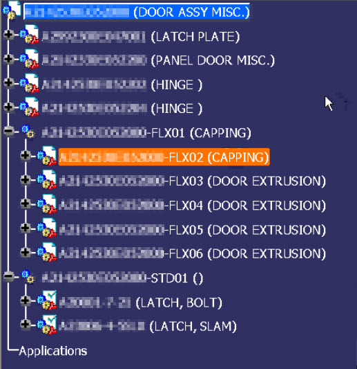 Finally, there might be parts in the CAD-structure that will not exist in reality as part but need to be created during the manufacturing process. Sheet metal parts are created during the manufacturing process. Cappings, strips and cables shown in the CAD-structure might come from materials that are purchased in standardized sizes (1 meter / 2 meter / 10 meter) and need to be cut during manufacturing. Here the instances in the CAD-structure will have a unique identifier. What type of identifier to use depends on the manufacturing process. It might be a physical part number, as it is a half-fabricate, or it remains a unique identifier for the CAD-structure only.
The reason I am coming back to these identifiers is that as described before, companies wanted to keep a relation between the part number and the file name.
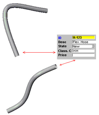 There was a problem with flexible parts. A rubber hose with a specific length could be shaped differently in an assembly based on its connection. Two different shapes would create two files and therefore break the rule of a part number equals file name. The 3D CAD vendors “solved” this issue by storing configurable views of the same part inside one file and allow the user to select the active view.
Later we will see that management of views inside the 3D CAD model is not a wrong choice. This, contrary to managing different configurations of a part/product inside a single file, which creates complexity in the PLM domain.
In the end, the product became an assembly with several levels of subassemblies. At that time, when I worked a lot with CAD-integrations, the average depth of 3D CAD-structures was 6 to 7 levels deep, with exceptions in both directions.
The entire product CAD-structure is mainly used for a final digital mock-up, to allow engineers to analyze the full product behavior. One of my favorite YouTube movies is the one from Airbus – seven years ago, they described the power of a full digital mock-up used for the A380.
In ETO-processes, the 3D CAD-structure is unique for a given customer solution – like the A380.
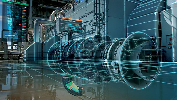 In the case of large assemblies with a lot of parts and subassemblies, there were situations where the full product could not be resolved anymore. For Airbus a must, for the mid-market not always easy to reach. Graphics memory, combined with the way graphics were represented, are the major constraint. This performance issue is resolved in the gaming world, however then the 3D representation had no longer the required accuracy or definition.
The Version pop-up problem
 Working with a 3D CAD structure created a new problem when designers were sharing parts and assemblies between themselves and suppliers. The central storage of the files required a versioning mechanism, supported by a check-in and check-out mechanism.
Depending on the type of 3D CAD integration, the PDM system generated a new minor revision of the file after check-in again. In this way, there was full traceability of the changes before release. The image below shows an example of how SmarTeam was dealing with minor and major revisions combined with lifecycle stages.
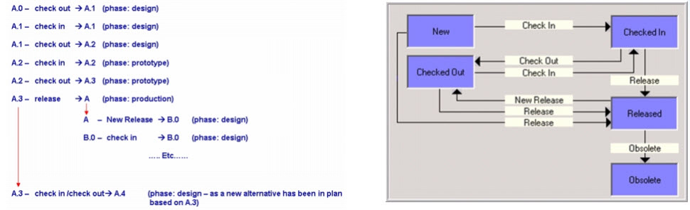
When revising a part, all assemblies that contained the changed part need to be updated too, in case you want to have traceability and preventing others from overwriting your version. Making sure this assembly file points to the right file again. In the cases of a 6-level deep CAD-structure, this has led to a lot of methodology problems on how to deal (or not to deal) with file changes.
In the case of a unique delivery for a customer, the ETO-process, the issue might not be so big. As everything in the 3D CAD-structure is work in progress, you only need to be sure during the release process of the 3D CAD-structure that all parts and assemblies are resolved to the latest version (and verified)
Making changes on an existing product is way more complicated, as assemblies are released, and parts exist in production. In that case, the Bill of Material is the leading structure to control the versions and the change impact, as we will see.
![]() Note: Most CAD- and PLM-vendors loved to show you their demos, where starting from the CAD-structure, a product gets created (the ETO-process). The reality is that most companies do not start from the CAD-structure, but from an existing Bill of Material. In 2010, I wrote a few posts, discussing the relation between CAD and the BOM:
Note: Most CAD- and PLM-vendors loved to show you their demos, where starting from the CAD-structure, a product gets created (the ETO-process). The reality is that most companies do not start from the CAD-structure, but from an existing Bill of Material. In 2010, I wrote a few posts, discussing the relation between CAD and the BOM:
to explain there is more than a CAD-driven scenario.
The EBOM
In most PDM-systems with CAD-integrations, it is possible to create a Bill of Materials from the 3D CAD-structure. The Bill of Materials will be based on the parts inside the 3D CAD-structure. There is often the option to filter out phantom assemblies.
The structures are not the same. The 3D CAD-structure is instance-based, where the extracted Bill of Materials will summarize the part quantities on the same level. See the image below. There are four Wheel instances in the CAD structure, in the EBOM-structure, we have only one Wheel reference with quantity 4.
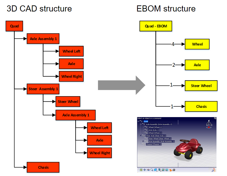
I named the structure on the right the EBOM as the structure represents the Bill of Materials from the engineering point of view. This definition is a little arbitrary, as we will see. In companies that started to develop products based on a conceptual BOM, often, this conceptual BOM was an “early” EBOM that had to be developed further. This EBOM was more representing a logical or modular structure driving the design, instead of an extract from the 3D CAD-structure. In the next post, I will zoom in on these differences. I want to conclude this time with a critical methodology needed to manage the 3D CAD structure changes in relation to an EBOM.
Breaking the rule Drawing ID (Model ID) = Part ID
Although I have been writing mostly about the 3D CAD structure, I want to remind us that the 3D Model in the mid-market is mainly used for design purposes. The primary delivery for manufacturing or a supplier is still a 2D-drawing for most companies. The 3D Model might be “nice to have” for CAM- or quality usage. Still, in case of a dispute, the 2D Drawing will be leading.
For that reason, in many mid-market companies, there was the following relation below:
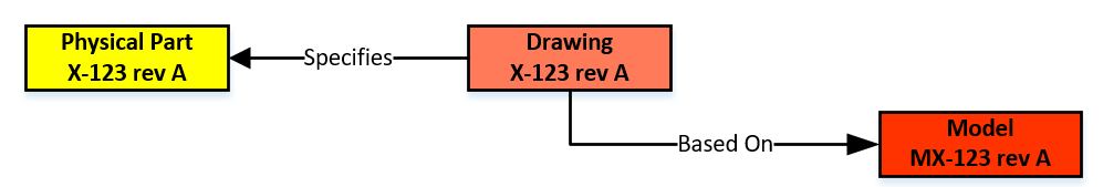
In an environment without file versioning through check-in/check-out, this relation was easy to maintain. In the electronic world, every change in the 3D Model (which could be an assembly) triggers a new file version and, therefore, most of the time, a new version of the drawing and the physical part. However, you do not want to have a physical part with many revisions, in particular when this part could be again part of a Bill of Material.
 To solve this issue, the Physical Part and the related Drawing/Model should have different lifecycles. The relation between the Physical Part and the Drawing Model should no longer be based on numbers but on a relation in the PDM/PLM-system. One of the main characteristics of a PDM/PLM-system is that it allows users to navigate through relations to find information in context. For example, solving a Where Used – question is a (few) mouse-click(s) in a PDM/PLM-system.
Click on the image to see the details.
Breaking this one-to-one numbering rule is a must if you want to evolve to an item-centric or data-driven PLM-environment. When to introduce this change and how to implement this new behavior is a methodology exercise, not an implementation of a new tool.
 There is a lot to read about this topic as it is related to the Form-Fit-Function-discussion we had earlier this year. A collection of information can be found in these two LinkedIn-post, where the comments are providing the insights:
- What the FFF is happening
- How to step beyond the complexity of Bill of Materials, Revisions and Change Management
I will not dive deeper into this theme (reached 1700 words ☹) – next time I will zoom in on the EBOM and leave the world of 3D CAD behind (for a while)
 To understand our legacy in the PLM-domain, what are the types of practices we created, I started this series of posts: Learning from the past to understand the future. My first post (The evolution of the BOM) focused on the disconnected world between engineering – generation of drawings as a deliverable – and execution MRP/ERP – the first serious IT-systems in a company.
At that time, due to minimal connectivity, small and medium-sized companies had, most of the time, an informal connection between engineering and manufacturing. I remember a statement at that time, PLM was just introduced. One person during a conference claimed:
“You guys make our lives so difficult with your systems. If we have a problem, we gather around the machine, and we fix it.”
PLM started at large enterprises
Of course, large enterprises could not afford such behavior as they operate globally. The leading enterprises for PDM/PLM were the Aerospace & Defense and Automotive companies. They needed consistent processes and formal ways of working to guarantee quality output.
 In that sense, I was happy with the reaction from Jean-Jacques Urban-Galindo, who shared in the LinkedIn comments a reference to a relevant chapter of John Stark’s PLM book. In the pdf describing the evolution of CAD / PDM / PLM at PSA. Jean-Jacques was responsible at that time for Responsible for the re-engineering of the Product & Process Engineering processes using digital tools (CAD/CAM, DMU, and more).
Read the PSA story here: PLM at GROUPE PSA. It describes nicely where 3D CAD and EBOM are coming in. In large enterprise like PSA, the need for tools are driven by the processes. When you read it to the end, you will also see the need for a design and a manufacturing view. A topic I will touch in future posts too.
The introduction of 3D CAD in the mid-market
 Where large automotive and aerospace companies already invested in (expensive) 3D CAD hard and software, for the majority of the midsize companies, the switch from 2D CAD (AutoCAD mainly) towards 3D CAD (SolidWorks, Solid Edge, Inventor) started at the end of the 20th century.
It was the time that Microsoft NT became a serious platform beside the existing mainframe and mini-computer based CAD-systems. The switch to PCs went so fast that the disruption from DEC (Digital Equipment Company) is one of the cases discussed by Clayton Christensen in his groundbreaking book: The Innovator’s dilemma
 3D CAD introduced a lot of new capabilities, like DMU (Digital Mock-Up), for clash detection, and above all, a better understanding of a product’s behavior. The introduction of 3D CAD introduced a new set of challenges to be resolved.
For example, the concept of reusing 3D CAD parts. Mid-market companies, most of the time, are buying productivity tools. Can I design my product faster and with higher quality in 3D instead of using only the 2D definitions?
Mid-market companies usually do not redesign their business processes – no people available for strategy – the pain of lack of strategy is felt in a different way compared to large enterprises—a crucial differentiator for the future of PLM.
Reuse of (3D) CAD parts / Assemblies
 In the 2D CAD world, there was not so much reuse of CAD parts. Standard parts were saved in libraries or generated on demand by parametric libraries. Now with 3D CAD, designers might spend more time to define the part. The benefits come from the reuse of small sub-assemblies (modules) into a larger product assembly. Something not relevant in the 2D CAD world.
 As every 3D CAD part had to have a file name, it became difficult to manage the file names without a system. How do you secure that the file with name Part01.xxx is unique? Another designer might also create an assembly, where the 3D CAD tool would suggest Part01.xxx as the name. And what about revisions? Do you store them in the filename, and how do you know you have the correct and latest version of the file?
Companies had already part naming rules for drawings, often related to the part’s usage similar to “intelligent” numbers I mentioned in my previous post.
With 3D CAD it became a little more complicated as now in electronic formats, companies wanted to maintain the relation:
Drawing ID = Part ID = File Name
The need for a PDM-system,
 If you look to the image on the left, which I found in one of my old SmarTeam files, there is a part number combined with additional flags A-A-C, which also have meaning (I don’t know ☹ ) and a description.
The purpose of these meaningful flags was to maintain the current ways of working. Without a PDM-system, parts of the assembly could be shared with an OEM or a supplier. File-based 3D CAD without using a PDM-system was not a problem for small and medium enterprises.
The 3D CAD-system maintained the relations in the assembly files, including relations to the 2D Drawings. Despite the introduction of 3D CAD, the 2D Drawing remained the deliverable the rest of the company or supply chain, was waiting for. Preferably a drawing containing a parts list and balloon numbers, the same as it has been done before. Why would you need a PDM-system?
PDM for traceability and reuse
 If you were working in your 3D CAD-system for a single product, or on individual projects for OEMs, there was no significant benefit for a PDM-system. All deliveries needed for the engineering department were in the 3D CAD environment. Assembly files and drawing files are already like small databases, containing references to the source files of the part (image above).
A PDM-system at this stage could help you build traceability and prevent people from overwriting files. The ROI for this part only depends on the cost and risks of making mistakes.
However, when companies started to reuse parts or subassemblies, there was a need for a system that could manage the 3D models separately. This had an impact on the design methodology.
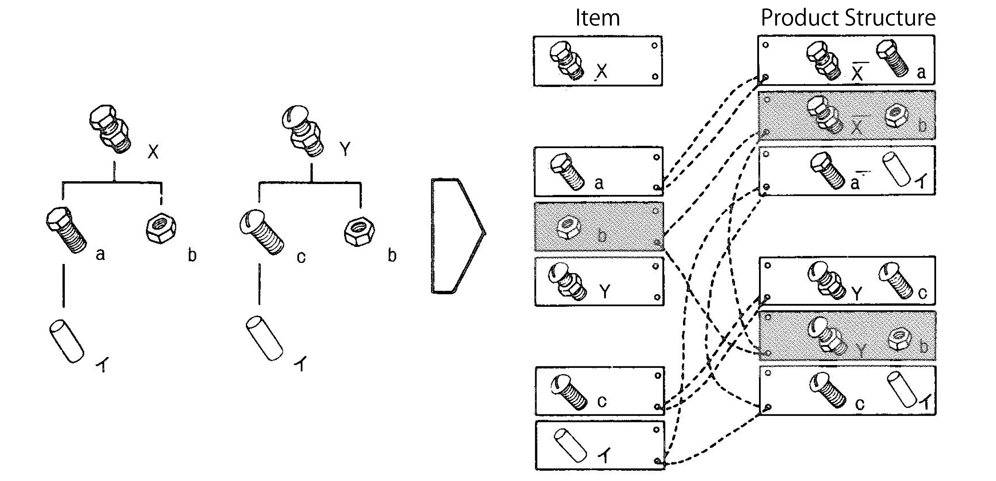 Now parts could be used in various products. How do you discover parts for reuse, and how do you know you have the last released version. For sure their naming cannot be related anymore to a single product or project (a practice still used a lot)
This is where PDM-systems came in. Using additional attributes per file combined with relations between parts, allowing companies to structure and deliver more details related to a part. A detailed description for internal usage, a part type (classification), and the part material were commonly used attributes. And not to forget the status and revision.
 For reuse, it was important that the creators of content had a strategy to define a part for future reuse or discovery. Engineerings were not used to provide such services, filling in data in a PDM-system was seen as an overhead – bureaucracy.
As they were measured on the number of drawings they produced, why do extra work with no immediate benefits?
The best compromise was to have the designer fill in properties in the CAD-file when creating a part. Using the CAD-integration with the PDM-system could be used to fill attributes in the PDM-system.
This “beautiful” simple concept lead later to a lot of complexity.
Is the CAD-model the source of data, meaning designers should always start from CAD when designing a product. If someone added or modified data in the PDM-system, should we open the CAD-file to update some properties? Changing a file means it is a new version. What happens if the CAD-file is released, and I update some connected attributes in PDM?
 To summarize this topic. Companies have missed the opportunity here to implement data governance. However, none of the silos (manufacturing preparation, service) recognized the need. Implementing new tools (3D CAD and PDM) did not affect the company’s way of working.
Instead of people, processes, tools, the only focus was on new tools and satisfying the people withing the same process.
 Of course, when introducing PDM, which happened for mid-market companies at the beginning of this century, there was no PLM vision. Talking about lifecycle support was a waste of time for management. As we will discover in the future posts, large enterprises and small and medium enterprises have the same PLM needs. However, there is already a fundamentally different starting point. Where large enterprises are analyzing and designing business processes, the small and medium enterprises are buying tools to improve the current ways of working
The Future?
 Although we have many steps to take in the upcoming posts, I want to raise your attention to an initiative from the PLM Interest Group together with Xlifecycle.com. The discussion is about what will be PLM’s role in digital transformation.
As you might have noticed, there are people saying the word PLM is no longer covering the right context, and all kinds of alternatives have been suggested. I recommend giving your opinion without my personal guidance. Feel free to answer the questionnaire, and we will be all looking forward to the results.
Find the survey here: Towards a digital future: the evolving role of PLM in the future digital world
Conclusion
We are going slow. Discovering here in this post the split in strategy between large enterprises (process focus) and small and medium enterprises (tool focus) when introducing 3D CAD. This different focus, at this time for PDM, is one of the reasons why vendors are creating functions and features that require methodology solving – however, who will provide the methodology.
Next time more on 3D CAD structures and EBOM
In my last post, My four picks from PLMIF, I ended with the remark that the discussion related to the Multiview BOM concept was not complete. The session presented by James Roche focused on the Aerospace & defense domain and touched the surface. There is a lot of confusion related to best practices associated with BOM-handling. Sometimes created to promote unique vendor capabilities or to hide system complexity.
Besides, we need to consider the past as, in particular, for PLM, the burden of legacy processes and data is significant. Some practices even come from the previous, paper-based century, later mixed with behavior from 3D CAD-systems.
 Therefore, to understand the future, I will take you through the past to understand why certain practices were established. Next, in a few upcoming posts, I want to explain the evolution of BOM-practices. How each new technology step introduced new capabilities that enabled companies to improve their product delivery process.
I will describe the drawing approach (for PLM – the past), the item-centric approach (for PLM – the current), and the model-driven approach(for PLM – the future). How big this sequence will become is not clear at this stage.
 Whenever I come close to 1200 – 1500 words, I will stop and conclude. Based on my To-do list and your remarks, I will continue in a follow-up post. The target will be to have a vendor-neutral collection of information to help you identify your business and the next possible steps.
Working with drawings

MRP/ERP – the first IT-system
For this approach, I go back fifty years in time, when companies were starting to work with their first significant IT-system, the MRP-system. MRP stands for Material Requirements Planning. This system became the heart of the company, scheduling the production. The extension to ERP (Enterprise Resource Planning) quickly after, made it possible to schedule other resources and, essential for the management, to report financials. Now execution could be monitored by generating all kinds of reports.
Still, the MRP/ERP-system was wholly disconnected from the engineering world as the image shows below. Let us have a look at how this worked at that time.

The concept
 Products have never been designed from scratch by jumping to drawings. In the concept phase, a product was analyzed, mainly on its mechanical behavior. Was there anything else at that time? Many companies thank their existence from a launching product which someone, most of the time, the founder of the company, invented in a workshop. The company than improved and enriched this product by starting from the core product, creating enhancements in various areas of applicability.
These new ideas were shared through sketches and prototypes.
The design
The detail design of a product is delivered by a technical documentation set, often a package of manufacturing drawings containing a list of parts on the drawing, assembly with instructions. Balloon numbers are used to indicate parts in an assembly or section view. In addition, there are the related fabrication drawings. The challenge for this approach is that all definitions must be there uniquely and complete to avoid ambiguity, which could lead to manufacturing errors.
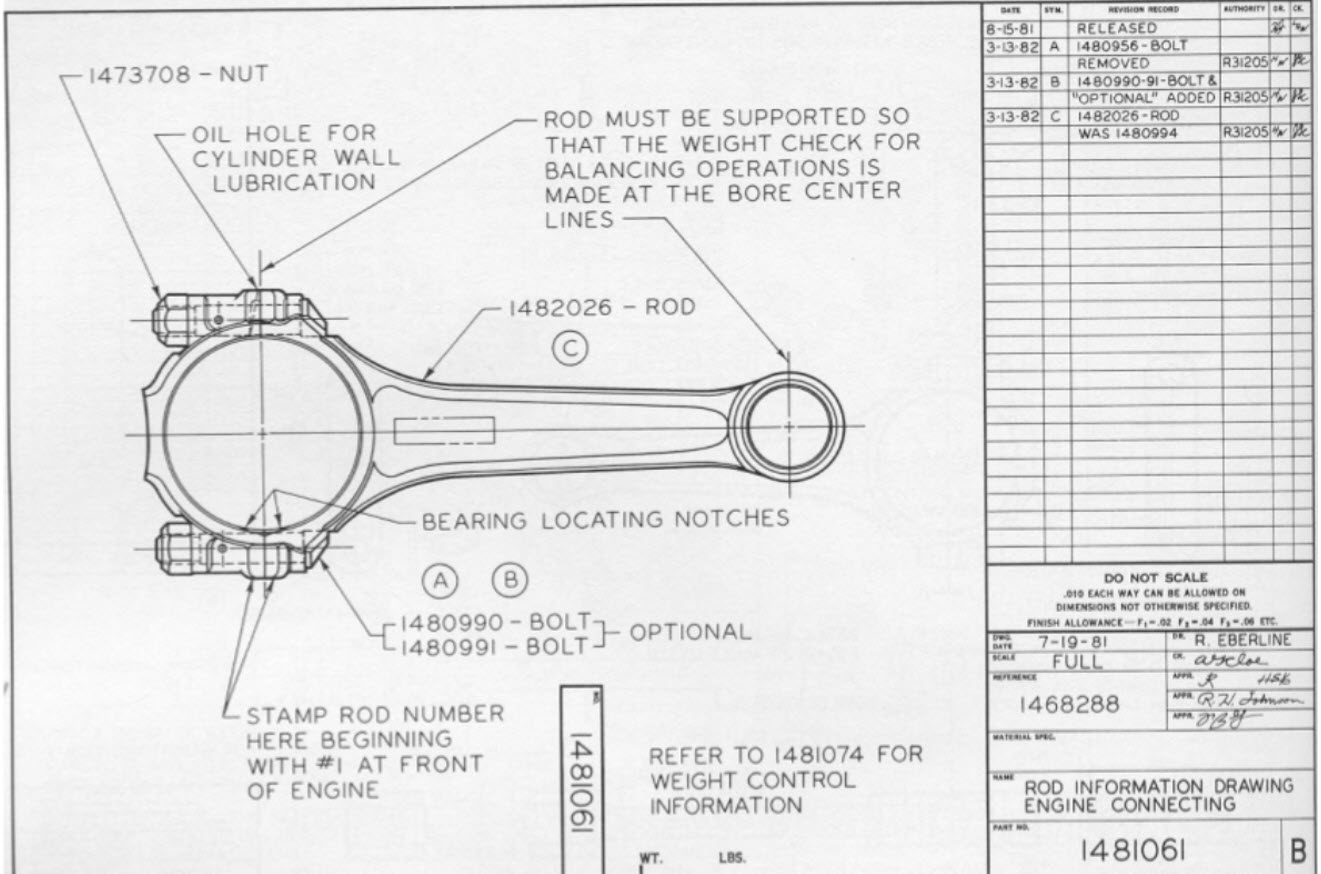
The parts list contains make-parts, supplier parts, and standard parts. The make-parts are specified again by manufacturing drawings, identified by a number that uniquely identifies the correct drawing version. A habit here: Part number = Drawing Number (+ revision)
![]() As the part is identified by a drawing the part most of the time got an “intelligent” part number and a revision. Intelligent to support easy recognition and revisions as at the end we do not want to generate a new part number when there is an evolution of the part. Read more about this in What the FFF is happening and “Intelligent” part numbers?
As the part is identified by a drawing the part most of the time got an “intelligent” part number and a revision. Intelligent to support easy recognition and revisions as at the end we do not want to generate a new part number when there is an evolution of the part. Read more about this in What the FFF is happening and “Intelligent” part numbers?
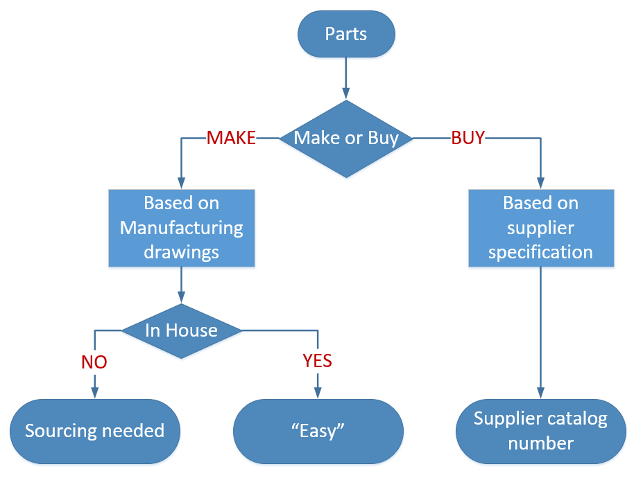 The standardized parts can be either company standard parts or external standard parts. There is a difference between them.
A company standard part could be a certain bracket, a frame. Anything that the company decided to standardize on for its own products Company standard parts are treated like make parts; they have an identifier related to their manufacturing drawings. Again, here the habit: Part Number = Drawing Number (+ revision)
The supplier part is coming from a supplier that manufactures this part based on the supplier or market specifications. You can specify this part by using the supplier’s catalog number or refer to the standard.
 For example, the part that has been specified under a certain ISO/ANSI/DIN-standard. For example, a stainless-steel bolt M8 x 1,25 x 20, meaning a metric bolt with a head diameter of 8 mm, a speed of 1,25 mm, and a length of 20 mm. You specify the standard part according to the standard. Purchasing will decide where to buy this part
Manufacturing Preparation
This is the most inefficient stage when working in a traditional drawing approach. At this stage, the information provided in drawings needs to be entered into the MRP/ERP-system to start production. This is the place where information is thrown over the wall as some might say.

This means a person needs to create process steps in the ERP-system based on the drawing information. For each manufacturing step, there needs to be a reference to the right drawing. Most ERP-systems have a placeholder where you can type the drawing number(s). Later, when companies were using CAD, there could be a reference to a file.
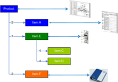 The part number in the ERP-system might be the same as the drawing number; however, the ERP-system requires unique numbers. In the beginning, ERP-systems were the number-generator for new parts. The unique number was often 6 to 7 digits in size, because it fits in our human short-term memory.
The parts list on the drawings had to be entered in the ERP-system too. A manual operation that often required additional research from the manufacturing engineer. As the designer might have specified the SS Bolt M8 x 1,25 x 20 as such, manufacturing preparation has to search in the ERP-system for the company’s part number.
Suppliers have to be sourced for outside manufactured make-parts. In case you do not want to depend on a single supplier, you have to send drawings and specifications to the supplier before the product is released. The supplier will receive a drawing number with revision and status warning.
If everything worked well the first time, there would be no iterations between engineering and manufacturing preparation. However, this is a utopia: prototype changes, potential manufacturing issues will require changes in the drawings. These changes require updates in the drawings, which will lead to new versions. How do you keep consistency between all identifiers?
Manufacturing
 During manufacturing, orders are processed based on information from the ERP-system. The shop floor gets the drawing provided to the link in ERP. Sometimes there are issues during manufacturing. In coordination with engineering, some adaptations will be made to the manufacturing process. e.g., a changed fit or tolerance. Instead of going back to engineering to provide a new documentation set, the relevant drawings are redlined. Engineering will update these drawings whenever they touch them in the future (yeah, yeah).
Configuration Management
But will they update them? Perhaps already a new version existed due to the product’s evolution. Everything needs to be coordinated manually. Smaller companies heavily rely on people knowing things and talking together.
Larger companies cannot work in the same manner; therefore, they introduce procedures to guarantee that the information flow is consistent and accurate. Here the practices from configuration management come in.
 There are many flavors of configuration management. Formal CM was first used in the 1950s to control the technical documentation for complex space and weapons systems. (Source ESA CM initiative for SME’s – © 2000) We will see it come back in future posts dealing with more complex products and the usage of computer systems.
Last year I wrote a few times about PLM and configuration management (PLM and CM – a happy marriage?) not relevant at this moment as there is no PLM yet.
Where is the BOM
As you might have noticed, there was no mentioning of a BOM so far. At this stage, there is only one Bill of Materials managed in the ERP-system. The source from the BOM comes from the various parts lists on the drawings, completed with manual additions.
 Nobody talks in this stage about an EBOM or MBOM as there is only one BOM, a kind of hybrid BOM, where manufacturing steps were driving the way parts are grouped. Because the information was processed step by step, why would you like to have a multilevel BOM or a BOM tree?
Note: The image on the left was one of my first images in 2008 when I started my blog.
Summary
Working with drawings introduced “intelligent” part numbers as the documents have to be identified by manual interpretations. The intelligence of the part number was there to prevent people from making mistakes as the number already was a kind of functional identifier. Combined with a revision and versioning in the number, nothing could go wrong if handled consistently.
 The disadvantage was that new employees had to master a numbering system. Next, the risk for all employees that a released drawing will not change its status. Only manual actions (retract/replace) will avoid making mistakes. And then, there are the disconnected redline drawings.
The “drawing number equals part number” relation created a constraint that will be hard to maintain in the future. Therefore you should worry if you still work according the above principles.
Conclusion
I reached the 1500 words – a long story – probably far from complete. I encourage readers to provide enhancements that might be relevant in the comments. This post might look like a post for dummies. However, to understand what is applicable to the future, we first need to understand why certain practices have been defined in the past.
I am looking forward to your comments and enhancements to make this a relevant stream of public information for all.
One week ago, Yoann Maingon wrote an innocent post with the question: Has FFF killed? The question was raised related to a 2014 problem at GM, where a changed part was causing fatal accidents.
 The discussion started by Yoann and here my short extract. Assuming this problem was a configuration management issue and Yoann somehow indicated that the problem might be related to the fact that ERP-systems do not carry a revision on the part number – leading to an unnoticed change. Therefore, he assumes there is a disconnect between the PLM-side (where we have parts with multiple lifecycle states and revisions) and ERP (where we have an industrial lifecycle – prototype/production).
He posted his thoughts, and then LinkedIn exploded (currently 116 comments), which means it is a topic that is of significant concern in our community. Next, if you read the comments, there are different viewpoints:
- What does FFF really imply?
- What about revisions of parts?
- What are the best practices?
Let’s investigate these viewpoints with some comments
What does FFF really imply?
When we talk about FFF in engineering, we mean Form, Fit and Function – the three primary characteristics to describe a part (source Wikipedia)
- Form refers to such characteristics as external dimensions, weight, size, and visual appearance of a part or assembly. This is the element of FFF that is most affected by an engineer’s aesthetic choices, including enclosure, chassis, and control panel, that become the outward “face” of the product.
- Fit refers to the ability of the part or feature to connect to, mate with, or join to another feature or part within an assembly. The “fit” allows the part to meet the required assembly tolerances to be useful.
- Function is a criterion that is met when the part performs its stated purpose effectively and reliably. In an electronics product, for example, a function can depend on the solid-state components used, the software or firmware, and quite often on the features of the electronics enclosure selected.
 One of the comments in Yoann’s post referred to Safe/Unsafe as a potential functional characteristic. I think this addition is not needed. Safety should be a requirement for the part, not a characteristic.
FFF was and still is an approach for engineers to decide if a new, improved version of the part would get a revision or needs a new part number.
I think before we dive deeper into the other viewpoints, it is crucial to define the part number a little more.
In a correct PLM data model, there are two types of part numbers. First, the internal part number that your company uses inside its engineering Bill of Materials to identify a part. This part number can be a meaningless part only to provide uniqueness inside the company.
In 2015 I wrote several posts related to best practices and data modeling for PLM. The most relevant posts to this discussion are here:
The part number can specify a part that needs to be manufactured according to specification, or it can be a part that needs to be purchased from an available supplier/manufacturer. The manufacturer part number is, most of the time, a meaningful number (6 – 7 characters) as these parts need to be ordered by your company. The manufacturer part number is the SKU for the manufacturer. As you can imagine in the manufacturer’s catalog, there isn’t a revision mentioned. In graphics, see the image below:

Your company might sell Product MP-323121 (note: the ID is meaningful to help the customer to order the product).
Internally there is a related EBOM that specifies the product. The EBOM top part is O122 (note: here, we can use a meaningless identifier as all is digitally connected).
For the manufacturing of O122, we need to resolve the EBOM according to its specifications. Therefore, for Part O124, the company needs to decide to purchase from their approved manufacturers either part ABC-21231 or XYZ-88818 (note: again, a meaningful ID as these companies are not digitally connected).
Now coming back to the FFF-discussion. For the orange parts, with a meaningful ID, no revision exists. However, if Assembly O122 is 100% FFF compatible, the Product ID MP-323121 will not change. It allows your company to optimize the EBOM and/or MBOM, meanwhile keeping 100% compatibility to the outside world. (note: the same principle applies to the two manufacturers for Part O124.)
In case Top Assembly O122 has new or changed parts – what should happen there?
 At that moment, the definition has changed. The definitions, most of the time described in documents/drawings/models, are related information to the BOM. Therefore the Top Assembly O122 should get a new identifier. There is no need to name it a revision, it is a new data set in the PLM-system, again with a meaningless identifier as we are connected digitally,
What about revisions of parts?
Of course, the management of changes existed long before PLM-systems were introduced.
 The specifications of a part were defined in drawings. The drawing contained all the information, not only the geometry definitions, but also specifications on how to manufacture the part.
For complex products, a considerable set of consistently related drawings would be released to manufacturing. A release process with physical signatures on it.
At the same time, there was no discussion: the drawing represents the part. And as there was no digital connection, part numbers/drawing numbers were meaningful, often with the format of the drawing as part of the identifier.
![]()
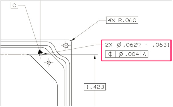 In case changes were needed, for example, fixing a dimension or tolerance as discovered during manufacturing, the drawing had to be revised to remain consistent. First, in the original drawing, the issue or change was marked in red (redlining). Then engineering had to create a new version of the drawing.
Depending on the impact of change (here comes also the FFF-principle), people decided if a new part number was needed (FFF-change) or that the change only required an update of the drawing(s), meaning a revision. If the difference was small (for example, adding a missing annotation), it could be called a minor change, all to be reflected in the drawing number, which equals the part number in this approach. So, when we talk about revisions of parts, we are talking about a document change.
A lousy practice from that approach is also that often manufacturing just redlines a drawing and keeps the redlined drawing as their source. It is too time-consuming or difficult to update the source drawing(s) through a change process. Engineering is not aware of this change, and when a later change comes through from engineering, these “fixes” might be missed as there is no traceability.
Generic example of a PLM data model and its relationsWhen PLM-systems were introduced, of course, companies did not want to disrupt their existing ways of working. Therefore, they were asking the PLM-editors to enable revisions on parts and so the PLM-editors did (or do).
Decoupling of parts and documents in a PLM data model
However, if you want to use the PLM-system in the best manner, you need to “decouple” the concept: part number equals drawing number, combined with the possibility to start using meaningless identifiers, as relations between parts and drawings are managed in the PLM-system through relational links.
Relevant post related to the PLM data model are:
- EBOM and (CAD) Documents
- Intelligent Part or Product numbers
- The impact of Non-Intelligent Part numbers
What are the best practices?
As some people mentioned in their comments to Yoann’s post, why do we have to answer this question as all is already well understood and described in best practices? I agree with that statement: Best Practices exist – so how to obtain them?
 First, there is the whole framework of Configuration Management, which existed long before PLM-systems were introduced. If you follow their methodology, you can be (almost) guaranteed your information is consistent and correct. Configuration Management is crucial in areas where the impact of an error is enormous, like the GM-example Yoann referred to. Also, companies in the Aerospace and Defense industry are the ones that have strict configuration management in place.
Configuration management does not come for free. It requires an investment in skills, potentially a change in ways of working, and requires an overhead. Manufacturing companies that are creating less “risky” products often focus more on optimizing (= reducing) the cost of their internal processes instead of investing in proper methodologies to manage consistency.
If you want to learn more about CM, investigate the Institute of Process Excellence (IPX), the founders of the CM2 framework for Enterprise Configuration Management, and much more. Note: Their knowledge does not come for free, which I can understand. However, it also creates a barrier for the company’s further investment in CM as this kind of strategic investments are hard to sell at the management level by individuals in a company.
 In the context of CM, I advise you to follow Martijn Dullaart, who is quite active in our social community. His latest blog post related to this thread is: It’s about Interchangeability and Traceability
With the introduction of PLM-system, these companies and the PLM-editors created the opportunity to implement configuration management in their system.
 The data inside the system would be the “single version of the truth.” Unfortunately, this was most of the time, just a sales strategy, falsely giving the impression that information is under control now. Last year I wrote several posts related to the relation between PLM and CM, starting from PLM and Configuration Management – a happy marriage?
If you are interested in another resource for information related to these topics, have a look at the website from Jörg Eisenträger who also collected his best practices for PLM and CM for sharing (thanks Paul van der Ree for the link)
Don’t expect best practices from your PLM-vendors as their role is to sell software. It is the continuous discussion between:
- A PLM-system that forces companies to work according to embedded methodology (hard to sell/implement but idealistically correct)
And
- A flexible PLM-system that allows you to build and configure anything (easy to sell/challenging to implement correctly, depending on “wise” decisions)
The Future
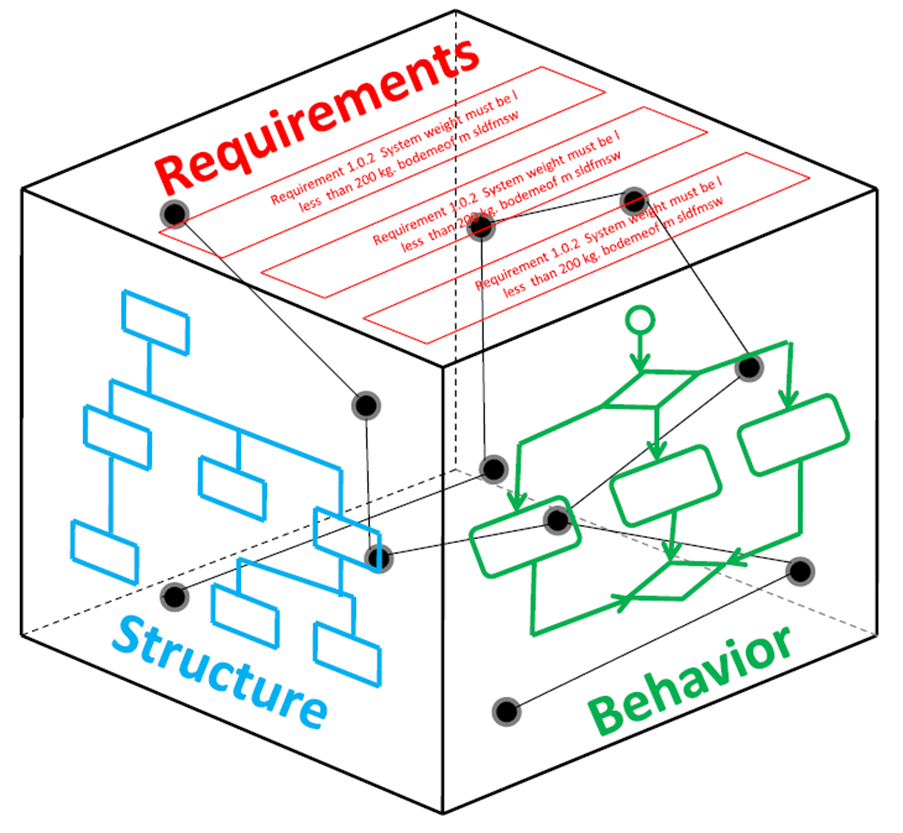 Even though most companies are working drawing-centric, with or without a linked PLM-backbone for BOM-management, the next upcoming challenge is to evolve to model-based practices. The current CM-practices still talk about documents, although documents are already electronic datasets in that context. The future, however, in a model-based enterprise evolves related to connected models, 3D Models, but also simulation and software models, with different lifecycles and pace of change. For the model-based enterprise, we need to develop digital best practices that guarantee the same level of quality, however, executed and/or supported by (AI) Artificial Intelligence. AI is needed as human beings cannot physically analyze and understand all the impact of a change in such an environment.
Conclusion
The FFF-discussion illustrates that building a consistent framework within PLM is not an easy goal to achieve. My blog buddy Oleg Shilovitsky would claim that we consultants create the complexity. PLM-editors will never solve this complexity, it is up to your company’s mission to invest in knowledge to understand why and how to reduce the complexity. With this post and the related links and discussions, I hope more clarity will help you to make “wise” decisions.

Hi Jos, Knowing your background in methodology and education, I wanted to share a longer article with you: “What is…
Interesting reflection, Jos. In my experience, the situation you describe is very recognizable. At the company where I work, sustainability…
[…] (The following post from PLM Green Global Alliance cofounder Jos Voskuil first appeared in his European PLM-focused blog HERE.) […]
[…] recent discussions in the PLM ecosystem, including PSC Transition Technologies (EcoPLM), CIMPA PLM services (LCA), and the Design for…
Jos, all interesting and relevant. There are additional elements to be mentioned and Ontologies seem to be one of the…