
You are currently browsing the category archive for the ‘PDM’ category.
 Over the last month, I have been actively engaged in the field; however, unfortunately, I have not been able to respond to all the interesting and sometimes humorous posts in my LinkedIn stream.
The fun started with a post from Oleg referring to a so-called BOM battle presented at Autodesk University by Gus Quade.
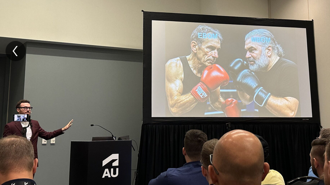
The image seems fake; however, the muscle power behind the BOM players looks real.
Prof. Dr. Jörg Fischer, also pictured, is advocating for rethinking PLM and BOM structures, and I share his discomfort.
Prof. Fischer wrote recently: “Forget everything you know about EBOM and MBOM. CTO+ is rewriting the rules of PLM. “
I am not a CTO expert, but I can grasp the underlying concepts and understand why it is closely associated with SAP. It aligns with the ultimate goal of maintaining a continuous flow of information throughout the company, with ERP (SAP?) at its core.
My question is, how far are we from that option?
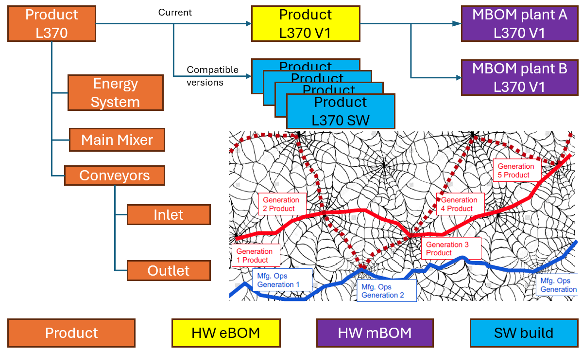
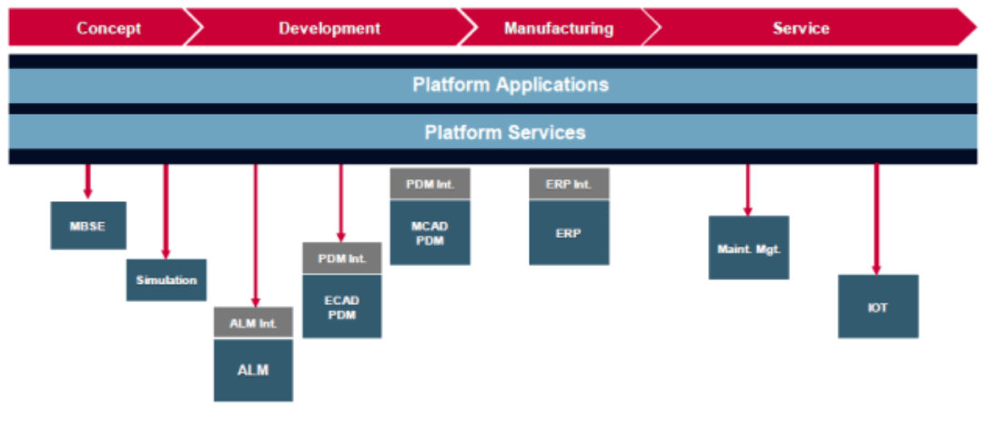
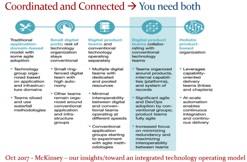
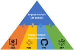
Current PLM implementations often focus on a linear process and data collection from left to right, as illustrated in the old Aras image below. I call this the coordinated approach.

 During the recent Dutch PLM platform meeting, we also discussed the potential need for an eBOM, mBOM, and potentially the sBOM. A topic many mid-sized manufacturing companies have not mastered or implemented yet – illustrating the friction in current businesses.
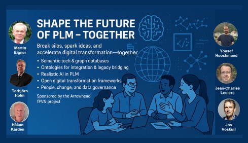
Meanwhile, we discuss agentic AI, the need for data quality, ontologies and graph databases. Take a look at the upcoming workshop on the Future of PLM, scheduled for November 4th in Paris, which serves as a precursor to the PLM Roadmap/PDT Europe 2025 conference on November 5th and 6th.
The reality in the field and future capabilities seem to be so far apart, which made me think about what the next step is after BOM management to move towards the future.
The evolution of the BOM
For those active in PLM, this brief theory ensures we share a common understanding of BOMs.
Level 0: In the beginning, there was THE BOM.
 Initially, the Bill of Materials (BOM) existed only in ERP systems to support manufacturing. Together with the Bill of Process (BOP), it formed the heart of production execution. Without a BOM in ERP, product delivery would fail.
Level 1: Then came a new BOM from CAD.
 With the rise of PDM systems and 3D CAD, another BOM emerged — reflecting the product’s design structure, including assemblies and parts. Often referred to as the CAD or engineering BOM, it frequently contained manufacturing details, such as supplier parts or consumables like paint and glue.
This hybrid BOM bridged engineering and manufacturing, linking CAD/PDM with ERP. Many machine manufacturers adopted this model, as each project was customer-specific and often involved reusing data by copying similar projects.
![]() Many industrial manufacturers still use this linear approach to deliver solutions to their customers.
Many industrial manufacturers still use this linear approach to deliver solutions to their customers.
Level 2: The real eBOM and mBOM arrived.
Later, companies began distinguishing between the engineering BOM (eBOM) and manufacturing BOM (mBOM), especially as engineering became centralized and manufacturing decentralized.

The eBOM represented the stable engineering definition, while the mBOM was derived locally, adapting parts to specific suppliers or production needs.
At the same time, many organizations aimed to evolve toward a Configure-to-Order (CTO) business model — a long-term aspiration in aligning engineering and manufacturing flexibility, as noted by Prof. Jörg Fischer in his CTO+ concept.
A side step: The impact of modularity
 Shifting from Engineer-to-Order (ETO) to Configure-to-Order (CTO) relies on adopting a modular product architecture. Modularity enables specific modules to remain stable while others evolve in response to ongoing innovation.
It’s not just about creating a 200% eBOM or 150% mBOM but about defining modules with their own lifecycles that may span multiple product platforms. Many companies still struggle to apply these principles, as seen in discussions within the North European Modularity (NEM) network.
See one of my reports: The week after the North European Modularity network meeting.
We remain here primarily in the xBOM mindset: the eBOM defines engineering specifications, while the mBOM defines the physical realization—specific to suppliers or production sites.
Level 3: Extending to the sBOM?
 To support service operations, the service BOM (sBOM) is introduced, managing serviceable parts and kits linked to the product. Managing service information in a connected manner adds complexity but also significant value, as the best margins often come from after-sales service.
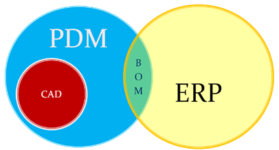
Click on the image above to understand the relations between the eBOM, mBOM(s) and sBOM.
 However, is the sBOM the real solution or only a theme pushed by BOM/PLM vendors to keep everything within their system? So far, this represents a linear hardware delivery model, with BOM structures tied to local ERP systems.
For most hardware manufacturers, the story ends here—but when software and product updates become part of the service, the lifecycle story continues.
The next levels: Software and Product Services require more than a BOM
 As I mentioned earlier, during the Dutch PLM platform discussion, we had an interesting debate that began with the question of how to manage and service a product during operation. Here, we reach a new level of PLM – not only delivering products as efficiently as possible, but also maintaining them in the field – often for many years.
There were two themes we discussed:
- The product gets physical updates and upgrades – how can we manage this with the sBOM – challenges with BOM versions or revisions ( a legacy approach)
- The product functions based on software-driven behavior, and the software can be updated on demand – how can we manage this with the sBOM (a different lifecycle)
The conclusion and answer to these two questions were:
We cannot use the sBOM anymore for this; in both cases, you need an additional (infra)structure to keep track of changes over time, I call it the logical product structure or product architecture.
The Logical Product Structure
 Since 2008, I have been involved in Asset Lifecycle Management projects, explaining the complementary value of PLM methodology and concepts related to an MRO environment, particularly for managing significant assets, such as those in the nuclear plants industry.
Historically, the configuration management of a plant was a human effort undertaken by individuals with extensive intrinsic knowledge.
A nuclear plant is an asset with a very long lifecycle that requires regular upgrades and services, and where safety is the top priority. However, thanks to digitization and an aging workforce, there was also a need to embed these practices within a digital infrastructure.
What I learned is that the logical product structure, also known as the plant breakdown structure (PBS), became an essential structure for combining the as-designed and as-operated structures of the plant.
In the SmarTeam image below, the plant breakdown structure was represented by the tag structure.

Coming back to our industrial products in service, it is conceptually a similar approach, albeit that the safety drivers and business margins might make it less urgent. For a product, there can also be a logical product structure that represents the logical components and their connections.
The logical structure of a product remains stable over time; however, specific modules or capabilities may be required, while the physical implementation (mBOM) and engineering definition (eBOM) may evolve over time.
Additionally, all relevant service activities, including issues and operational and maintenance data, can be linked to the logical structure. The logical structure is also the structure used for a digital twin representation.
The logical product structure and software
The logical product structure is also where hardware and software meet. The software can be managed in an ALM environment and provides traceability to the product in service through the product structure.
Note: this is a very simplified version, as you can imagine, it looks more like a web of connected datasets – the top level shows the traceability between the various artifacts – HW and SW
Where is the product structure defined?
The product structure originates from a system architect, and it depends on the tools they are using, where it is defined – historically in a document, later in an Excel file – the coordinated approach.
In a modern data-driven environment, you can find the product structure in an MBSE environment and then connect to a PLM system – the federated and connected approach.
There are also PLM vendors that have the main MBSE data elements in their core data model, reducing the need for building connectivity between the main PLM and MBSE elements. In my experience, the “all-in-one” solutions still underperform in usability and completeness.
Conclusion
I wrote this post to raise awareness that a narrow focus on BOM structures can create a potential risk for the future. Changing business models, for example, the product-service system, require a data-driven infrastructure where both hardware and software artifacts need to be managed in context. Probably not in a single system but supported by a federated infrastructure with a mix of technologies. And I feel sorry that I could not write about a model-based enterprise at this time!
I am looking forward to discussing the future of PLM with a select group of thought leaders on November 4th in Paris, as a precursor to the upcoming PLM Roadmap/PDT Europe conference. For the workshop on November 4th, we almost reached our maximum size we can accommodate, but for the conference, there is still the option to join us.
Please review the agenda and join us for engaging and educational discussions if you can.
And if you are not tired of discussing PLM as a term, a system or a strategy – watch the recording of this unique collection of PLM voices moderated by Michael Finochario.
After a summer holiday in the south of Greece, it is time to resume my activities. The south of Crete is largely an analogue environment, far from any digital hype.
 Tempted by LinkedIn posts, I noticed the summer was full of memories, with Martin Eigner sharing 40 years of PLM experience, Oleg Shilovitsky sharing 30 years of PDM Evolution, and Michael Finochario publishing posts on PLM vendors, CAD kernels, and more.
So where do I stand? While digesting all these historical experiences, I reflected on what we can learn from them and what we didn’t learn from them.
It started with technology.
 From 1990 to 1999, I worked with mid-market companies, where data management was the most significant challenge. The introduction of MS Windows made data management more user-friendly, evolving from drawing management systems with version and status management capabilities.
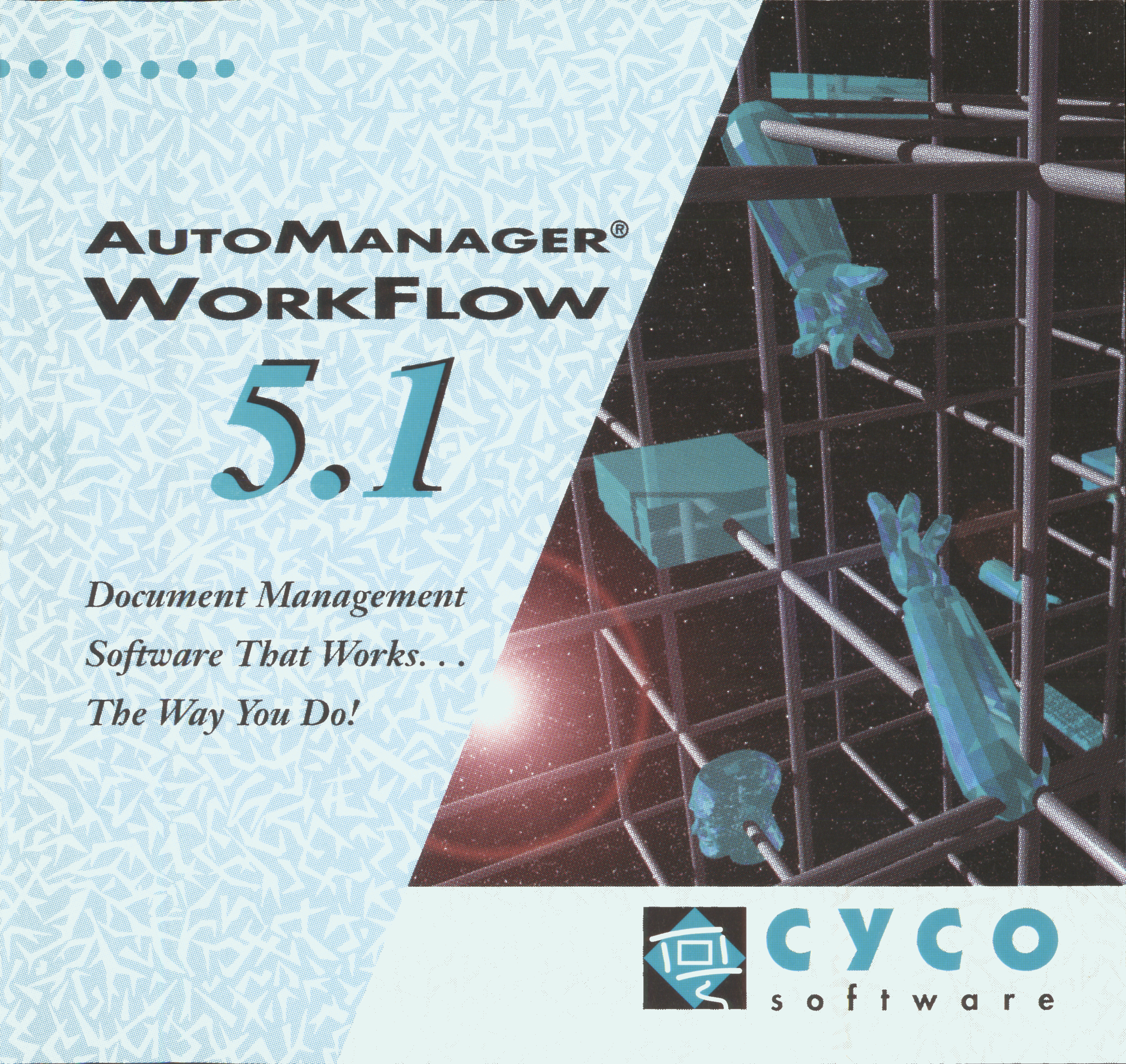
Who remembers Automanager Workflow from Cyco, before SmarTeam came on the market?
For that reason, in the early days, PDM was an IT job. As the PDM system primarily dealt with engineering data, it was relatively easy to implement as an organizational change process. We transitioned from analogue to electronic in the department.
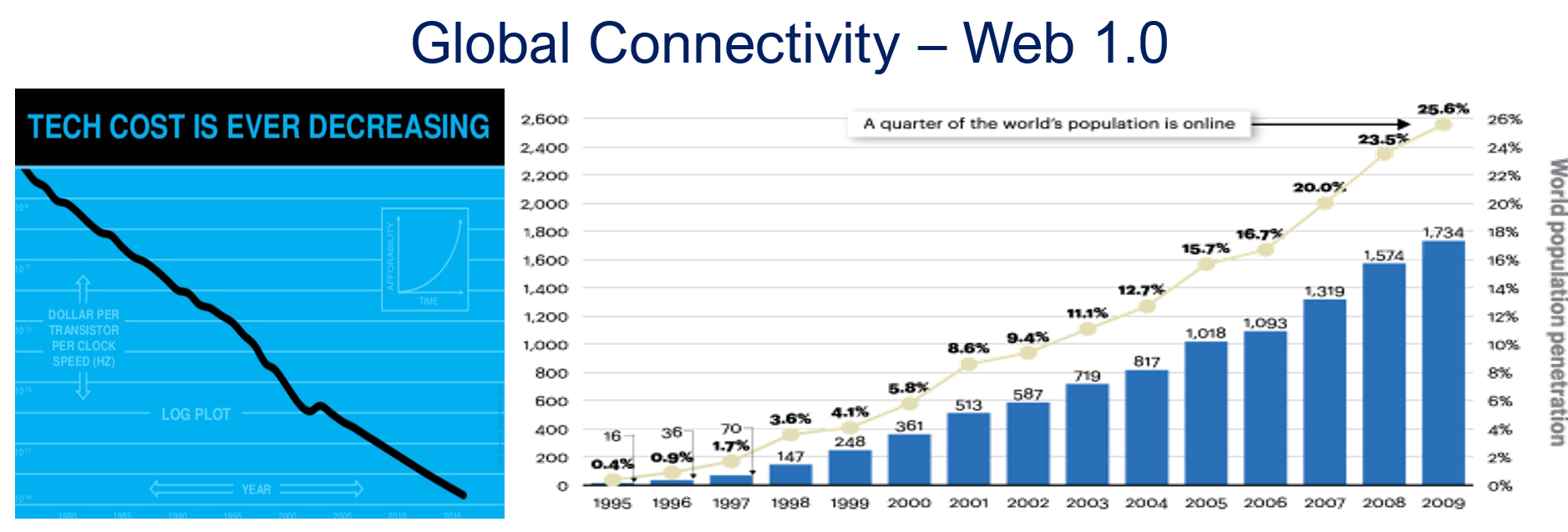
Connecting with other systems, particularly ERP, was a serious IT job and a financial challenge. Connecting with other systems, particularly ERP, was a serious IT job and a financial challenge. The rapid decline of IT components, combined with the rapid growth of global connectivity, has created new opportunities for collaboration.
As part of the Dassault/IBM/SmarTeam organization, I explained and taught these new capabilities worldwide.
 In 2008, my VirtualDutchman blog and coaching journey began, evolving from explanations of technology to modern methodologies, which led to organizational change and expectation management – skills not traditionally associated with IT.
Then came digital transformation
With growing connectivity, smartphones and Web 2.0 technology have led to more PLM-like discussions. PLM vendors expanded their scope and developed capabilities beyond mechanical engineering.
 The expansion of capabilities was also the moment when the confusion about the term PLM reached its peak: a PLM strategy or a PLM system?
At the time, they were largely considered the same in discussions and advertisements..
Meanwhile, digital transformation was occurring at the marketing and sales levels – companies invested in direct communication with their customers through the web.
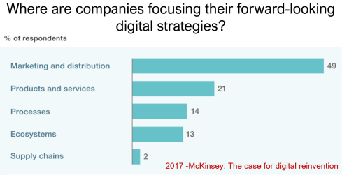
Meanwhile, the internal ways of working for R&D, engineering, and manufacturing did not change significantly. Still, they were following linear processes, and despite the existence of 3D CAD, the 2D drawing remained the primary carrier of legal information between engineering, manufacturing, and suppliers.
Note: the option where the most benefits could be achieved – connected supply chains – had the lowest focus in 2017 – something that would change with COVID-19.
Fundamental digital transformation in the PLM domain occurred gradually. ARAS came with its overlay approach (the platform), connecting various disciplines and enterprise systems. In contrast, Dassault Systèmes introduced its 3DEXPERIENCE platform, utilizing its own software brands as platform components.
The Aras overlay approach
Most PLM vendors rapidly countered Aras’ overlay approach with their low-code offerings based on Mendix, ThingWorx or Netvibes, to enable data flows beyond the traditional PDM scope. The Coordinated Digital Thread was born.
The good news is that PLM has now clearly become a strategy based on a federated system infrastructure. The single PLM system no longer exists, although many of us still use the term’ PLM system’ to refer to the main component of a PLM infrastructure – the System of Record.
Moving to a federated PLM infrastructure is already a challenge for companies, not because of the available technology, but first of all because of the legacy data and, closely related to that, legacy processes and people skills.
Legacy is creating the inertia, not technology!
Next came the cloud – SaaS
 With the availability of cloud solutions that support real-time interactions between stakeholders, either within an enterprise or in a value chain, a new paradigm has emerged: the connected enterprise.
A connected enterprise no longer needs interfaces to transfer data from one system to another.
Instead, with apps and dashboards, combined data from different online sources is presented in a single, user-friendly working environment – A combination of the Systems of Record with the new environments – the Systems of Engagement.
The technology used to create dashboards and apps is based on modern data-driven technologies and principles (ontologies, graph databases, and the semantic web). The Connected Digital Thread was born.
However, legacy systems play an essential role again, as some systems of engagement can be implemented in a complementary manner to the systems of record, allowing companies to work within an integrated technology model.
People will work in a particular mode, either coordinated or connected, but organizations can operate in both modes simultaneously. A story I have been sharing a lot – it is not about migrations but about an evolutionary approach towards an integrated technology model.
At this point, it becomes essential that business objectives drive the implementation of a PLM infrastructure. Of course, you hear me say we should start from the business; however, the big difference now is that a company should coordinate the technologies, systems, and tools it acquires to avoid isolated islands of information.
Follow Yousef Hooshmand‘s 5 + 1 business transformation steps.

 An open SaaS infrastructure enables a company to let data flow almost in real-time. There is a lot of discussion related to data quality and governance, and if you have missed it, please read these three articles I created together with Rob Feronne, the product Digital PLuMber:
- Data Quality and Data Governance – A hype? (part 1)
- Data Quality and Data Governance – the WHY and HOW (part 2)

- Building the Future: Data Quality and Governance in the Digital Age (part 3)
There are some great insights in this dialogue and the associated LinkedIn comments.
Despite the increasing availability of technology, it is the legacy of people, processes, and culture that is hindering progress.
Rob Feronne had a shocking lightbulb moment 😲 in our discussion about the future of PLM, where the participants – see below – answered a question related to the importance of technology in our PLM domain – shocking also for me.
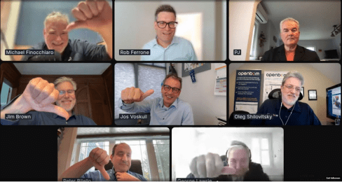
My thumb was up because modern technology matters! The question inspired Oleg Shilovitsky to write a whole blog post on this topic. If you’re truly shocked, read his post, where I agree with the content; the question is too simple to answer with a thumbs up/down.
 As technology has become more accessible than before, you no longer need an IT department to establish a PLM infrastructure. And then indeed, the people and process side needs and deserves much more attention..
And now there is AI
 If you haven’t read anything about AI recently, you must be living in an isolated location. Regardless of the business discussions you are following, it is all about the potential of AI.
Although AI is not a new concept, the fact that various AI capabilities have now reached the end-user level is what drives the hype. Currently, I believe we are at the peak of the hype.
Last week, I participated in an interesting discussion in the series: The Future of PLM moderated by Michael Finochario, this time talking with the analysts. Click on the link to see Michael’s excellent summary and access to the recording of the event.

It was an interesting discussion for a little more than an hour, and the majority of our discussion was about the potential impact of AI on businesses. First, the impact AI can have on the traditional work of an analyst and next, the effects on the PLM domain.
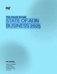 I believe we agreed that AI at this moment is mainly providing higher user efficiency and performance, very much aligned with the interesting research I have been reading in the MIT NANDA report with the title The GenAI Divide: STATE OF AI IN BUSINESS 2025
The report’s interesting findings included high adoption of tools but low transformation. Despite significant investment in Generative AI (GenAI), most organizations are not achieving meaningful business transformation.
- 95% of organizations report zero return on GenAI investments.
- Only 5% of integrated AI pilots generate millions in value.
- 80% of organizations have explored or piloted tools like ChatGPT, but these primarily enhance individual productivity.
- 60% of organizations evaluated enterprise-grade systems, but only 20% reached the pilot stage, and just 5% reached production.
- Key barriers include brittle workflows, a lack of contextual learning, and operational misalignment.
Therefore, the question is – Is current AI the next bubble?
In 2014, I wrote about the lack of digital transformation in the PLM domain, and two images (below) from a report by The Economist could be used again. The report can be found here: The Onrushing Wave.
Click on the image to read the 2013 predictions.
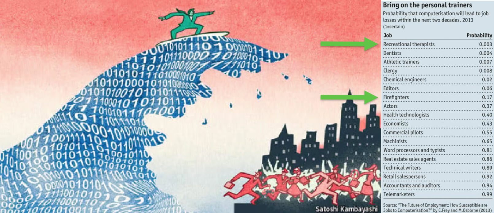
I realized that my current job, as a recreational therapist and firefighter at the time, was not at risk, and that some of the predictions from 10 years ago had become a reality. Who is still bothered by telemarketers or retail salespersons?
However, many of the AI symptoms mentioned in the MIT NANDA report are similar to the hype surrounding digital transformation.
The only reservation I have now – will it take a decade before we understand and demonstrate the value of AI, or are we accelerating?
In this context, the upcoming PLM Roadmap/PDT Europe conference on 5 – 6 November will be interesting, as here we will discuss reality.
For a few of you interested in more, there is the day before the conference, a (free) workshop where we will discuss with some thought leaders and experts from various companies how the future of PLM could look like – based on standards, AI tools and more. Click on the image below the conclusion.
Conclusion
The summertime was a nice moment to reflect, inspired by others in my network. What is clear is that there is a shift from technology towards people and change. The rapid expansion of AI tools, along with connected technologies, has created an overwhelming array of possibilities. Now it is time for business leadership to understand them and utilize them for significant business improvement, where the fear is that substantial change will always be slowed down by organizational inertia.
 In the past months, I have had several discussions related to migrating PLM data, either from one system to another or from consolidating a collection of applications into a single environment. Does this sound familiar?
Let me share some experiences and lessons learned to avoid the Migration Migraine.
It is not a technical guide but a collection of experiences and thoughts that you might have missed when considering to solve the technical dream.
 Halfway I realized I was too ambitious; therefore, another post will follow this introduction. Here, I will focus on the business side and the digital transformation journey.
Garbage Out – Garbage In
 The Garbage Out-In statement is somehow the paradigm we are used to in our day-to-day lives. When you buy a new computer, you use backup and restore. Even easier, nowadays, the majority of the data is already in the cloud.
This simple scenario assumes that all professional systems should be easily upgrade-able. We become unaware of the amount of data we store and its relevance.
This phenomenon already has a name: “Dark Data.” Dark Data consumes storage energy in the cloud and is no longer visible. Please read all about it here: Dark Data.
 TIP 1: Every migration is a moment to clean up your data. By dragging everything with you, the burden of migrating becomes bigger. In easy migrations, do a clean-up—it prevents future, more extensive issues.
Never follow the Garbage Out – Garbage in principle, even if it is easy!
Migrations in the PLM domain are different – setting the scene.
 Before discussing the various scenarios, let’s examine what companies are doing. For early PLM adopters in the Automotive, Aerospace, and Defense Industries, migrations from mainframes to modern infrastructures have become impossible. The real problem is not only the changing hardware but also the changing data and data models.
For these companies, the solution is often to build an entirely new PLM infrastructure on top of the existing infrastructure, where manageable data pieces are migrated to new environments using data lakes, dashboards, and custom apps to support modern users.
Migration in this case is a journey as long as the data lives – and we can learn from them!
Follow the money
 From a business perspective, migrations are considered a negative distractor. Talking about them raises awareness of their complexity, which might jeopardize enthusiasm.
For the initiator, the PLM software vendor or implementer, it might endanger the sales deal.
Traditional IT organizations strive for simplification—one CAD, one PLM or one ERP system to manage. Although this argument makes sense, an analysis should always be done comparing the benefits and the (migration) costs and risks to reach the ideal situation.
In those discussions often, migrations are downplayed

Without naming companies, I have observed the downplaying several times, even at some prominent enterprises. So, if you recognize your company in this process, you are not alone.
TIP 2: Migrations are never simple. Make migration a serious topic of your PLM project – as important as the software. This approach means analyzing the potential migration risks and their mitigation is needed.
Please read about the Xylem story in my recent post: The week after the PDSFORUM 2024
The Big Bang has the highest risk and might again lead to garbage out—garbage in.
You are responsible for your garbage.
It may sound disparaging, but it is not. Most companies are aware that people, tools and policies have changed over the years. Due to the coordinated approach to working, disciplines did not need to care about downstream or upstream usage of their initially created data – Excel and PDFs are the bridges between disciplines.

All the actual knowledge and context are stored in the heads of experienced employees who have gotten used to dealing with inconsistencies. And they will retire, so there is an urgent need for actual data quality and governance. Read more about the journey from Coordinated to Connected in these articles.
Even if you are not yet thinking about migrations, the digital transformation in the PLM domain is coming, and we should learn to work in a connected mode.
TIP 3: Create a team in your organization that assesses the current data quality and defines the potential future enterprise (data) architecture. Then, start improving the quality of the current generated data. Like the ISO 900x standard, the ISO 8000 standard already exists for data quality.
The future is data-driven; prepare yourself for the future.
Migration scenarios and their best practices
Here are some migrations scenario’s – two in this post and more in an upcoming post.
From Relational to Object-oriented
 One of my earlier projects, starting in 2010 with SmarTeam, was migrating a mainframe-based application for airplane certification to a modern Microsoft infrastructure.
The goal was to create a new environment that could be used both as a replacement for the mainframe application and as the design and validation environment to implement changes to the current airplanes during a maintenance or upgrade activity.
The need was high because detailed documentation about the logic of the current application did not exist, and only one person who understood the logic was partly available.
So, internally, the relational database was a black box. The tables in the database contained a mix of item data, document data, change status and versions. The documents were stored in directories with meaningful file names but disconnected from the application.

The initial estimate was that the project would take two to three months, so a fixed price for two months was agreed upon. However, it became almost a two-year project, and in the end, the result seemed to be reliable (there was never mathematical proof).
 The disadvantage was that SmarTeam ended up being so highly customized that automatic upgrades would not work for this version anymore—a new legacy was created with modern technology.
The same story, combined with the example of Ericsson’s migration attempt, is described in the 2016 post, The PLM Migration Dilemma. For me, the lesson learned from these examples leads to the following recommendation.
TIP 4: When there is a paradigm change in the data model, don’t migrate but establish a new (data-driven) infrastructure and connect to your legacy as much as possible in read-only mode.
The automotive and aerospace industries’ story is one of paradigm change.
 Listen to the SharePLM podcast Revolutionizing PLM: Insights from Yousef Hooshmand, where Yousef also discusses how to address this transition process.
CAD/PDM to PLM
Another migration step happens when companies decide to implement a traditional PLM infrastructure as a System of Record, merging PDM data (mainly CAD) and ERP data (the BOM).
Some of these companies have been working file-based and have stored their final CAD files in folders; others might have a local PDM system native to the 3D CAD. The EBOM usually existed digitally in ERP, and most of the time, it is not a “pure” EBOM but more of a hybrid EBOM/MBOM.

The image above show this type of migration can be very challenging as, in the source systems, there is not necessarily a consistent 3D CAD definition matching the BOM items. As the systems have been disconnected in the past, people have potentially added missing information or fixed information on the BOM side. As in most companies, the manufacturing definition is based on drawings, and the consistency with the 3D CAD definition is not guaranteed.
To address this challenge, companies need to assess the usability of the CAD and BOM data. Is it possible to populate the CAD files with properties that are necessary for an import? For example, does the file path contain helpful information?
 I have experienced a situation where a company has poorly defined 3D parts and no properties, as all the focus was on using the 3D to generate the 2D drawing.
The relevant details for manufacturing were next added to the drawing and not anymore to the parts or models – traceability was almost impossible.
In this situation, importing the 3D CAD structures into the new PLM system has limited value. An alternative is to describe and test procedures for handling legacy data when it is needed, either to implement a design change or a new order. Leave the legacy accessible, but do not migrate.
The BOM side is, in theory, stable for manufactured products, as the data should have gone through a release process. However, the company needs to revisit its part definition process for new designs and products.
Some points to consider:
- Meaningful identifiers are not desired in a PLM system as they create a legacy. Therefore, the import of parts with smart identifiers should map to relevant part properties besides the ID. Splitting the ID into properties will create a broader usage in the future. Read more in Smart Part Numbers – do we need them?

- In addition, companies should try to avoid having logistic information, such as supplier-specific part numbers to come from the CAD system. Supplier parts in your CAD environment create inefficiencies when a supplier part becomes obsolete. Concepts such as EBOM and MBOM and potentially the SBOM should be well understood during this migration.

- Concepts of EBOM and MBOM should also be introduced when moving from an ETO to a CTO approach or when modularity is a future business strategy.


Conclusion
As every company is on its PLM journey and technology is evolving, there will always be a migration discussion. Understanding and working towards the future should be the most critical driver for migration. Migrations in the PLM domain are often more than a data migration – new ways of working should be introduced in parallel. And for that reason the “big bang” is often too costly and demotivating for the future.
 On March 22 this year, I wrote Time to Think (and act differently) in de middle of a changing world. We were entering a lockdown in the Netherlands due to the COVID-19 virus. As it was such a disruptive change, it was an opportunity to adapt their current ways of working.
The reason for that post was my experience when discussing PLM-initiatives with companies. Often they have no time to sit down, discuss and plan their PLM targets as needed. Crucial people are too busy, leading to an implementation of a system that, in the best case, creates (some) benefits.
 The well-known cartoon says it all. We are often too busy doing business as usual, making us feel comfortable. Only when it is too late, people are forced to act. As the second COVID-19 wave seems to start in the Netherlands, I want to look back on what has happened so far in my eco-system.
Virtual Conferences
As people could not travel anymore, traditional PLM-conferences could not be organized anymore. What was going to be the new future for conferences? TECHNIA, apparently clairvoyant, organized their virtual PLM Innovation Forum as one of the first, end of April.

A more sustainable type of PLM-conference was already a part of their plans, given the carbon footprint a traditional conference induces. The virtual conference showed that being prepared for a virtual conference pays off during a pandemic with over 1000 participants.
Being first does not always mean being the best, as we have to learn. While preparing my session for the conference, I felt the same excitement as for a traditional conference. You can read about my initial experience here: The weekend after the PLM Innovation Forum.
Some weeks later, having attended some other virtual conferences, I realized that some points should be addressed/solved:
- Video conferencing is a must – without seeing people talking, it becomes a podcast.
- Do not plan long conference days. It is hard to sit behind a screen for a full day. A condensed program makes it easier to attend.
- Virtual conferences mean that they can be attended live from almost all around the globe. Therefore, finding the right timeslots is crucial for the audience – combined with the previous point – shorter programs.
- Playing prerecorded sessions without a Q&A session should be avoided. It does not add value.
- A conference is about networking and discussion – I have not seen a solution for this yet. Fifty percent of the conference value for me comes from face-to-face discussions and coffee meetings. A virtual conference needs to have private chat opportunities between attendees.
In the last quarter of this year, I will present at several merely local conferences, sometimes a mix between “live” with a limited number of attendees, if it will be allowed.
And then there is the upcoming PLM Road Map & PDT Fall 2020 (virtual) conference on 17-18-19 November.

This conference has always been my favorite conference thanks to its continued focus on sharing experiences, most of the time, based on industry standards. We discuss topics and learn from each other. See my previous posts: The weekend after 2019 Day 1, 2019 Day 2, 2018 Day 1, 2018 Day2, 2017 Day 1, 2017 Day 2, etc.
The theme Digital Thread—the PLM Professionals’ Path to Delivering Innovation, Efficiency, and Quality has nothing to do with marketing. You can have a look at the full schedule here. Although there is a lot of buzz around Digital Thread, presenters discuss the reality and their plans
Later in this post, see the paragraph Digital Thread is not a BOM, I will elaborate on this theme.
Getting tired?
 I discovered I am getting tired as I am missing face-to-face interaction with people. Working from home, having video calls, is probably a very sustainable way of working. However, non-planned social interaction, meeting each other at the coffee machine, or during the breaks at a conference or workshop, is also crucial for informal interaction.
Apparently, several others in my eco-system are struggling too. I noticed a tsunami of webinars and blog posts where many of them were an attempt to be noticed. Probably the same reason: traditionally businesses have stalled. And it is all about Digital Transformation and SaaS at this moment. Meaningless if there is no interaction.

My favorite quote:
I still meet people that continue to express beliefs about the world, their industry, their customers or their own performance that simply aren’t true. Although some, like Steve Jobs, were known for their “reality distortion field,” for virtually all of us, just wishing for something to be true doesn’t make it so. As William Edwards Deming famously said: in God we trust; all others must bring data.
I fully concur with this statement and always get suspicious when someone claims the truth.
Still, there are some diamonds.
I enjoyed all episodes from Minerva PLM TV – Jennifer Moore started these series in the early COVID19-days (coincidence?). She was able to have a collection of interviews with known and less-known people in the PLM-domain. As most of them were vendor-independent, these episodes are a great resource to get educated.

The last episode with Angela Ippisch illustrates how often PLM in companies depends on a few enthusiastic persons, who have the energy to educate themselves. Angela mentions there is a lot of information on the internet; the challenge is to separate the useful information from marketing.
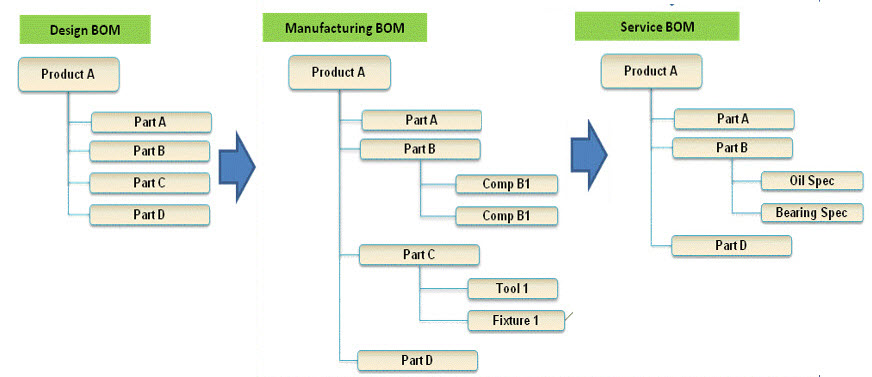
 I have been publishing the past five months a series of posts under the joint theme learning from the past to understand the future. In these posts, I explained the evolution from PDM to PLM, resulting in the current item-centric approach with an EBOM, MBOM, and SBOM.
On purpose, one post per every two weeks – to avoid information overflow. Looking back, it took more posts than expected, and they are an illustration of the many different angles there are in the PLM domain – not a single truth.
Digital Thread is not a BOM
I want to address this point because I realized that in the whole blogging world there appear to be two worlds when discussing PLM terminology. Oleg Shilovitsky, CEO@OpenBOM, claims that Digital Thread and Digital Twin topics are just fancy marketing terms. I was even more surprised to read his post: 3 Reasons Why You Should Avoid Using The Word “Model” In PLM. Read the comments and discussion in these posts (if LinkedIn allows you to navigate)
![]() Oleg’s posts have for me most of the time, always something to discuss. I would be happier if other people with different backgrounds would participate in these discussions too – A “Like” is not a discussion. The risk in a virtual world is that it becomes a person-to-person debate, and we have seen the damage such debates can do for an entire community.
Oleg’s posts have for me most of the time, always something to discuss. I would be happier if other people with different backgrounds would participate in these discussions too – A “Like” is not a discussion. The risk in a virtual world is that it becomes a person-to-person debate, and we have seen the damage such debates can do for an entire community.
In the discussion we had related to Digital Thread and BOM, I realized that when we talk about traditional products, the BOM and the Digital Thread might be the same. This is how we historically released products to the market. Once produced, there were no more changes. In these situations, you could state a PLM-backbone based on BOM-structures/views, the EBOM, MBOM, and SBOM provide a Digital Thread.
The different interpretation comes when talking about products that contain software defining its behavior. Like a computer, the operating system can be updated on the fly; meanwhile, the mechanical system remains the same. To specify and certify the behavior of the computer, we cannot rely on the BOM anymore.
Having software in the BOM and revise the BOM every time there is a software change is a mission impossible. A mistake suggested ten years ago when we started to realize the different release cycles of hardware and software. Still, it is all about the traceability of all information related to a product along its whole lifecycle.
 In a connected environment, we need to manage relationships between the BOM and relations to other artifacts. Managing these relations in a connected environment is what I would call the Digital Thread – a layer above PLM. While writing this post, I saw Matthias Ahrens’ post stating the same (click on the image to see the post)
 When we discuss managing all the relations, we touch the domain of Configuration Management. Martijn Dullaart/Martin Haket’s picture shares the same mindset – here, CM is the overlapping layer.
However, in their diagram, it is not a system picture; the different systems do not need to be connected. Configuration Management is the discipline that maintains the correct definition of every product – CM maintains the Thread. When it becomes connected, it is a Digital Thread.
As I have reached my 1500 words, I will not zoom in on the PLM and Model discussion – build your opinion yourself. We have to realize that the word Model always requires a context. Perhaps many of us coming from the traditional PDM/PLM world (managing CAD data) think about CAD models. As I studied physics before even touching CAD, I grew up with a different connotation
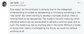 Lars Taxén’s comment in this discussion perhaps says it all (click on the image to read it). If you want to learn and discuss more about the Digital Thread and Models, register for the PLM Roadmap & PDT2020 event as many of the sessions are in this context (and not about 3D CAD).
Conclusion
I noticed I am getting tired of all the information streams crying for my attention and look forward to real social discussions, not broadcasted. Time to think differently requires such discussion, and feel free to contact me if you want to reflect on your thoughts. My next action will be a new series named Painting the future to stay motivated. (As we understand the past).
 Already five posts since we started looking at the roots of PLM, where every step illustrated that new technical capabilities could create opportunities for better practices. Alternatively, sometimes, these capabilities introduced complexity while maintaining old practices. Where the previous posts were design and engineering-centric, now I want to make the step moving to manufacturing-preparation and the MBOM. In my opinion, if you start to manage your manufacturing BOM in the context of your product design, you are in the scope of PLM.
For the moment, I will put two other related domains aside, i.e., Configuration Management and Configured Products. Note these domains are entirely different from each other.
Some data model principles
 In part five, I introduced the need to have a split between a logical product definition and a technical EBOM definition. The logical product definition is more the system or modular structure to be used when configuring solutions for a customer. The technical EBOM definition is, most of the time, a stable engineering specification independent of how and where the product is manufactured. The manufacturing BOM (the MBOM) should represent how the product will be manufactured, which can vary per location and vary over time. Let us look in some of the essential elements of this data model
The Product
 The logical definition of the product, which can also be a single component if you are a lower tier-supplier, has an understandable number, like 6030-10B. A customer needs to be able to order this product or part without a typo mistake. The product has features or characteristics that are used to sell the product. Usually, products do not have a revision, as it is a logical definition of a set of capabilities. Most of the time, marketing is responsible for product definition. This would be the sales catalog, which can be connected in a digital PLM environment. Like the PDM-ERP relation, there is a similar discussion related to where the catalog resides—more on the product side later in time.
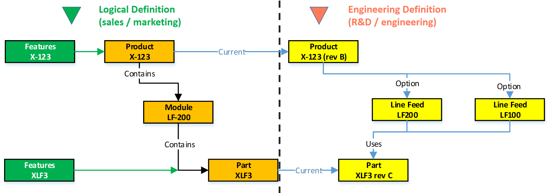
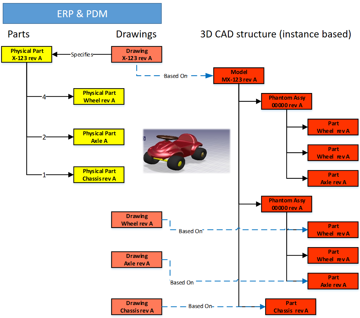
The EBOM
Related to the product or component in the logical definition, there is an actual EBOM, which represents the technical specification of the product. The image above shows the relation represented by the blue “current” link.
 Note: not all systems will support such a data model, and often the marketing sides in managed disconnected from the engineering side. Either in Excel or in a specialized Product Line Engineering (PLE) tools.
We discussed in the previous post that if you want to minimize maintenance, meaning fewer revisions on your EBOM, you should not embed manufacturer-specific parts in your EBOM.
 The EBOM typically contains purchase parts and make parts. The purchased parts are sourced based on their specification, and you might have a single source in the beginning. The make parts are entirely under your engineering control, and you define where they are produced and by whom. For the rest, the EBOM might have functional groupings of modules and subassemblies that are defined for reuse by engineering.
 Note: An EBOM is the place where multidisciplinary collaboration comes together. This post mainly deals with the mechanical part (as we are looking at the past)
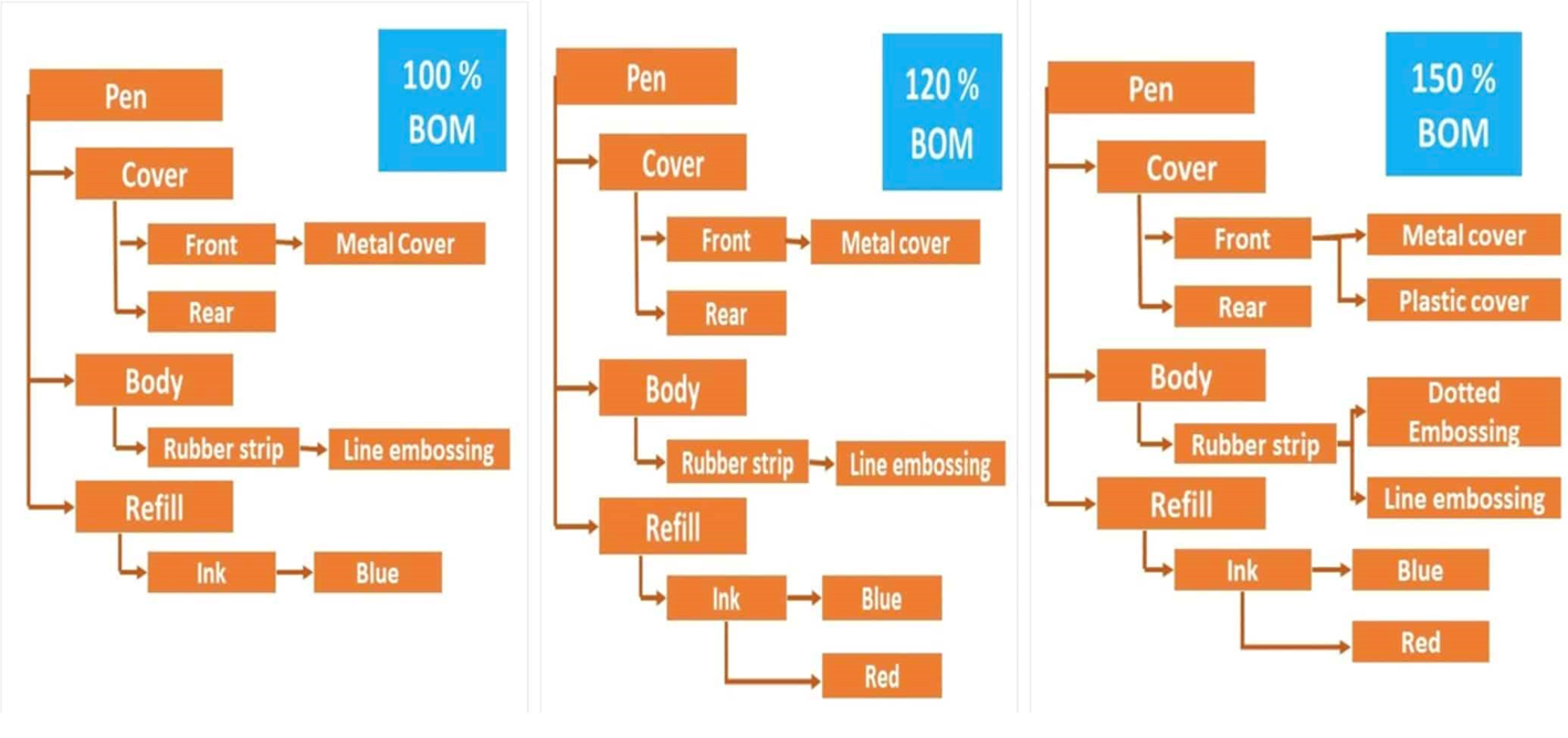
Note: An EBOM can contain multiple valid configurations which you can filter based on a customer or market-specific demand. In this case, we talk about a Configured EBOM or a 150 % EBOM.
The MBOM
 The MBOM represents the way the unique product is going to be manufactured. This means the MBOM-structure will represent the manufacturing steps. For each EBOM-purchase-part, the approved manufacturer for that plant needs to be selected. For each make-part in the EBOM, if made in this plant per customer order, the EBOM parts need to be resolved by one or more manufacturing steps combined with purchased materials.
Let us look at some examples:
The flat MBOM
Some companies do not have real machinery anymore in their plants, the product they deliver to the market is only assembled at the best financial location. This means that all MBOM-parts should arrive at the shop floor to be assembled there. As an example, we have plant A below.
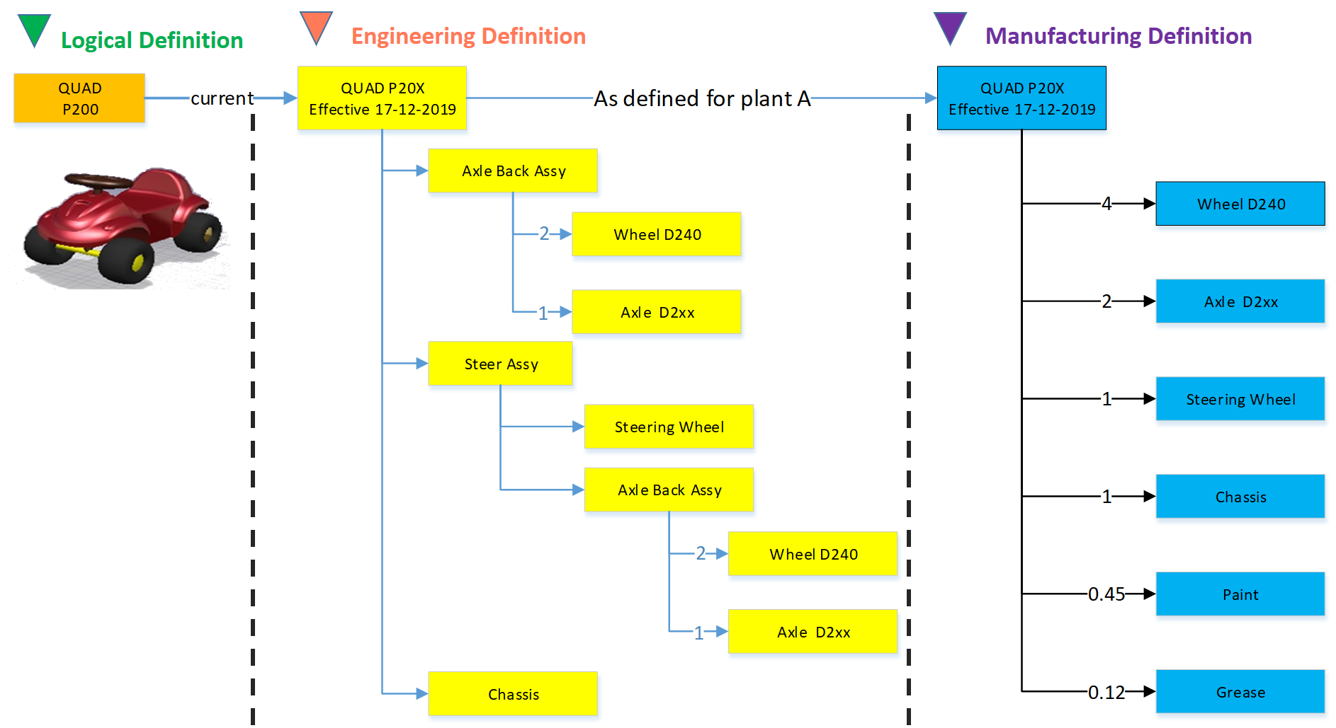
Of course, this is a simplified version to illustrate the basics of the MBOM. The flat MBOM only makes sense if the product is straightforward to assemble. Based on the engineering specifications, the assembly drawing(s) people on the shop floor will know what to do.
The engineering definition specifies that the chassis needs to be painted, and fitting the axles requires grease. These quantities are not visible in the EBOM; they will appear in the MBOM. The quantities and the unit of measure are, of course, relevant here.
Note: The exact quantities for paint and grease might be adjusted in the MBOM when a series of Squads have been manufactured.
The MBOM and Bill of Process
Most of the time, a product is manufactured in several process steps. For that reason, the MBOM is closely related to the Bill of Process or the Routing definitions. The image below illustrates the relationship between an MBOM and the operations in a plant.
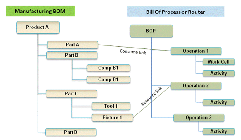
If we continue with our example of the Squad, let us now assume that the wheels and the axle are joined together in a work cell. In addition, the chassis is painted in a separate cell. The MBOM would look like the image below:

In the image, we see that the same Engineering definition now results in a different MBOM. A company can change the MBOM when optimizing the production, without affecting the engineering definition. In this MBOM, the Axle assembly might also be used in other squads manufactured by the company.
The MBOM and purchased parts
 In the previous example, all components for the Squad were manufactured by the same company with the option to produce in Plant A or in Plant B. Now imagine the company also has a plant C in a location where they cannot produce the wheels and axle assembly. Therefore plant C has to “purchase” the Wheel-Axle assembly, and lucky for them plant B is selling the Wheel+Axle assembly to the market as a product.
The MBOM for plant C would look like the image below:
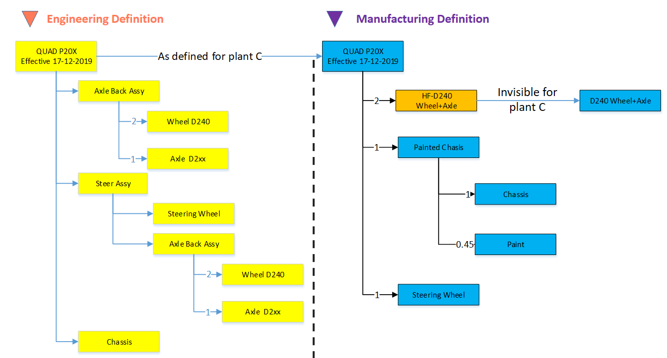
For Plant C, they will order the right amount of the Wheel+Axle product, according to its specifications (HF-D240). How the Wheel+Axle product is manufactured is invisible for Plant C, the only point to check is if the Wheel+Axle product complies with the Engineering Definition and if its purchase price is within the target price range.
Why this simple EBOM-MBOM story?
 For those always that have been active in the engineering domain, a better understanding of the information flow downstream to manufacturing is crucial. Historically this flow of information has been linear – and in many companies, it is still the fact. The main reason for that lies in the fact that engineering had their own system (PDM or PLM), and manufacturing has their own system (ERP).
Engineers did their best to provide the best engineering specification and release the data to ERP. In the early days, as discussed in Part 4, the engineering specification was most of the time based on a kind of hybrid BOM containing engineering and manufacturing parts already defined.
 Next, manufacturing engineering uses the engineering specifications to define the manufacturing BOM in the ERP system. Based on the drawings and parts list, they create a preferred manufacturing process (MBOM and BOP) – most of the time, a manual process. Despite the effort done by engineering, there might be a need to change the product. A different shape or dimension make manufacturing more efficient or done with existing tooling. This means an iteration, which causes delays and higher engineering costs.
The first optimization invented was the PDM-ERP interface to reduce the manual work and introduction of typos/misunderstanding of data. This topic was “hot” between 2000 and 2010, and I visited many SmarTeam customers and implementers to learn and later explain that this is a mission impossible. The picture below says it all.
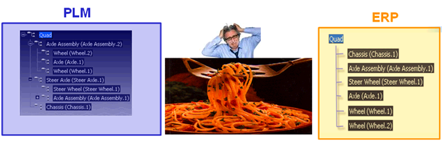
We have an engineering BOM (with related drawings). Through an interface, this EBOM will be restructured into a manufacturing BOM, thanks to all kinds of “clever” programming based on particular attributes. Discussed in Part 3
 The result, however, was that the interface was never covering all situations and became the most expensive part of the implementation.
Good business for the implementing companies, bad for the perception of PDM/PLM.
The lesson learned from all these situations: If you have a PLM-system that can support both the EBOM and MBOM in the same environment, you do not need this complex interface anymore. You can still use some automation to move from an EBOM to an MBOM.
However, three essential benefits come from this approach
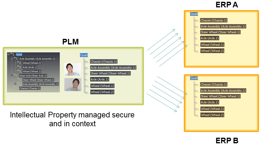
- Working in a single environment allows manufacturing engineers to work directly in the context of the EBOM, proposing changes to engineering in the same environment and perform manual restructuring on the MBOM as programming logic does not exist. Still, compare tools will ensure all EBOM-parts are resolved in the manufacturing definition.
- All product Intellectual Property is now managed in a single environment. There is no scattered product information residing in local ERP-systems. When companies moved towards multiple plants for manufacturing, there was the need for a centralized generic MBOM to be resolved for the local plant (local suppliers / local plant conditions). Having the generic MBOM and Bill of Process in PLM was the solution.
- When engineers and manufacturing engineers work in the same environment, manufacturing engineering can start earlier with the manufacturing process definition, providing early feedback to engineering even when the engineering specification has not been released. This approach allows real concurrent engineering, reducing time to market and cost significantly
Conclusion
Again 1600 words this time. We are now at the stage that connecting the EBOM and the MBOM in PLM has become a best practice in most standard PLM-systems. If implemented correctly, the interface to ERP is no longer on the critical path – the technology never has been the limitation – it is all about methodology.
Next time a little bit more on advanced EBOM/MBOM interactions
In this post in the series Learning from the past to understand the future, I want to leave the 3D CAD structures behind. But before doing so, I want to mention some of the lessons learned:
![]() In Part 1: “Intelligent” drawing numbers were the source for “intelligent” part numbers as often there was a one-to-one relationship between the drawing and the part(s) on a drawing.
In Part 1: “Intelligent” drawing numbers were the source for “intelligent” part numbers as often there was a one-to-one relationship between the drawing and the part(s) on a drawing.
 In Part 2: 3D CAD has been introduced in the automotive and aerospace industry due to process optimization, where a 3D CAD environment created better collaboration possibilities (DMU). The introduction of 3D CAD in the mid-market was different. Here 3D CAD is used as an engineering tool, not changing any processes.
The complexity grew because also file names needed to be managed, introducing the need for PDM-systems.
![]() In Part 3: we discussed the challenges of working with file-based 3D CAD structures. The versioning problem with check-in/check-out of structure in particular in the case of data reuse. Here the best practice was introduced to have physical parts with a different lifecycle than 3D CAD parts and assemblies.
In Part 3: we discussed the challenges of working with file-based 3D CAD structures. The versioning problem with check-in/check-out of structure in particular in the case of data reuse. Here the best practice was introduced to have physical parts with a different lifecycle than 3D CAD parts and assemblies.
Now engineers need to create valid configurations based on links between the physical part and the 3D/2D object. This requires a PDM-system with BOM and CAD-files as standard information objects.
 In Part 4: we discussed the relations between the BOM and 3D CAD structures without neglecting the fact the 2D Drawing is still the primary legal information carrier for manufacturing/suppliers. The point discussed in this post was the fact that most companies used a kind of ETO-approach. Starting from the 3D CAD-system, adding sometimes manufacturing parts in this structure, to generate a BOM that can be served as input for the ERP-system.
I want to follow up from the last conclusion:
Changing from ETO to CTO requires modularity and a BOM-driven approach. Starting from a 3D CAD-structure can still be done for the lowest levels – the modules, the options. In a configure to order process, it might not be relevant anymore to create a full 3D-representation of the product.
Starting from a conceptual structure
 Most companies that deliver products to the market do not start from scratch, as we discussed. They will start from either copying an existing product definition (not recommend) or trying to manage the differences between them, meanwhile keeping shared components under revision control.
 This cannot be done based on 3D CAD-structures anymore. At that time (we are in the early 2000s) in the mid-market, the PDM-system was used to manage these structures, in particular, they used the BOM-capabilities.
The BOM-structure was often called the EBOM, as engineers were defining the EBOM. But is it really an EBOM? Let us have a look wat defines an EBOM.
What characterizes an EBOM?
There are many personal definitions of what is considered as an EBOM. Also, the Wiki-definition here does not help us a lot. So here is my personal 2004 definition:
- The EBOM reflects the engineering view of a product and, therefore, can have a logical structure of assemblies and subassemblies based on functionality, modularity, and standardization.
- The EBOM is a part structure specifying a product from its design intent, specifying parts, materials, tolerances, finishing.
- The EBOM-structure is allowing multidisciplinary teams to work together on a joint definition of the product
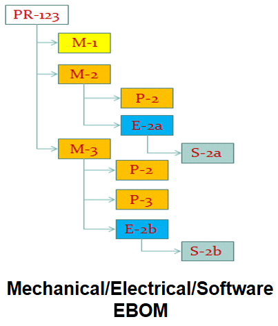
The picture below illustrates the above definition.
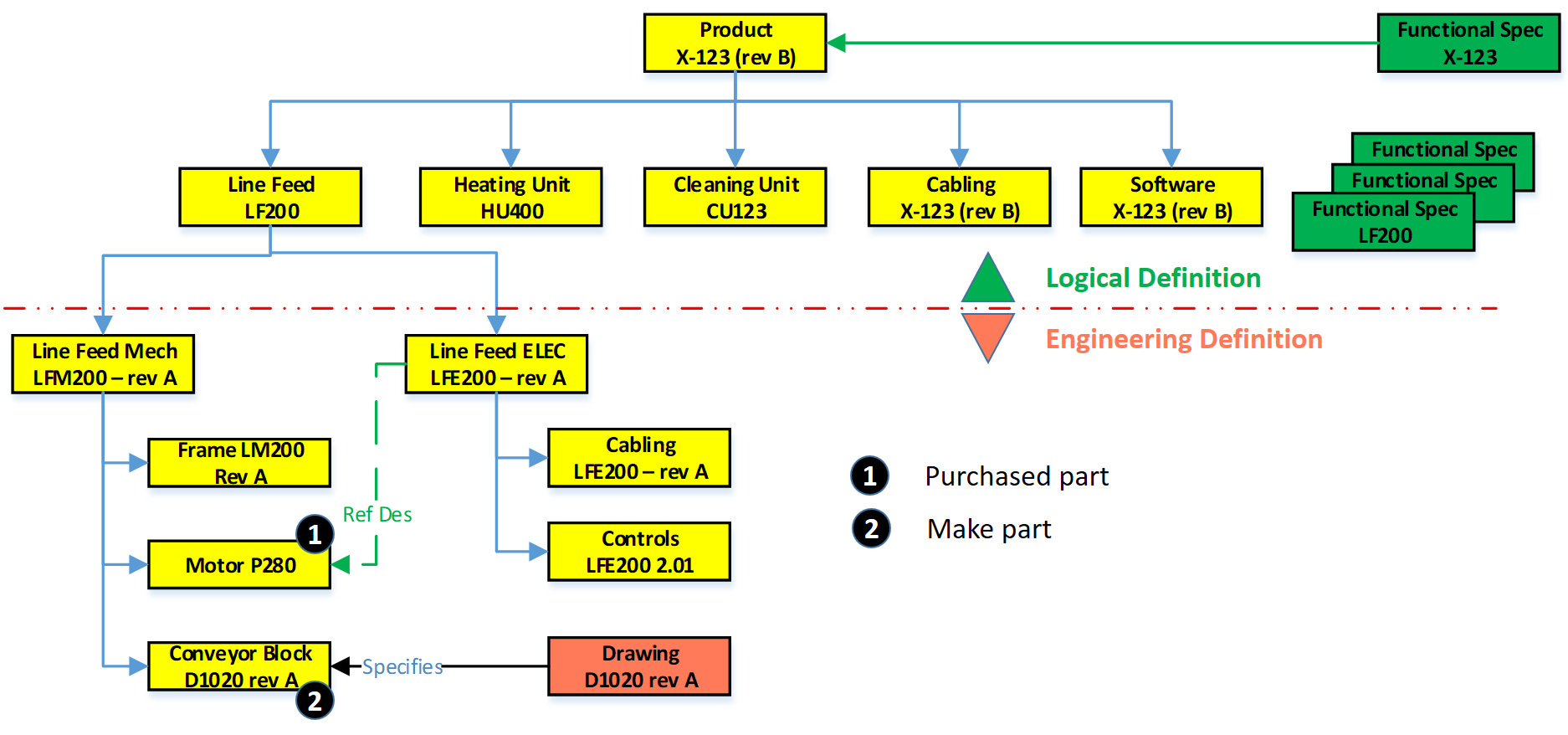
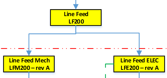
In this EBOM-structure, we see that the first two levels actually are more a logical division of functional groups, either as units, product/discipline-specific definitions (cabling/software). These components should not be in the EBOM if you have support for logical structures in your PLM-environment. However, in 2004 – PLM was not that mature in the mid-market, and this approach was often chosen.
If we look at the Line Feed module, which could also be used in other products, there is the typical mechanical definition and in parallel the electrical definition. Having them inside a single EBOM gives the advantage of being able to do a “where-used” and status/impact-analysis.
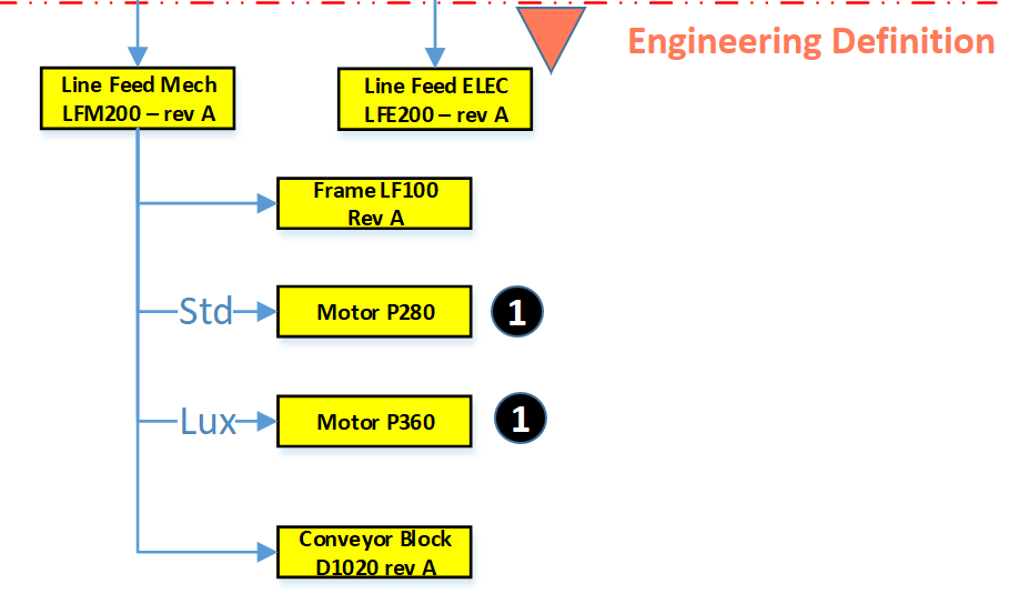
1 – Purchased parts
 Motor P280 is an interesting EBOM-part to consider. This motor is required; however, in an EBOM, you should not specify the supplier part number directly. As supplier part availability and preference will change over time, you do not want to revise the EBOM every time a supplier part gets changed.
 Therefore, the Motor P280 should have an internal part number in the EBOM. Next, it will be engineering that specifies which motors fulfill the need for Motor P280. Preferably they will create an Approved Manufacturing List for this motor to give manufacturing/purchasing the flexibility to decide per order where to purchase the motor and from which supplier.
The relation between the Approved Manufacturing List and the Approved Vendor List is shown in the diagram above.
![]() Or follow the link to this image to read more in Arena’s glossary. In particular, for electronic components, this concept is needed as high-level specifications for electronic parts might be the same.
Or follow the link to this image to read more in Arena’s glossary. In particular, for electronic components, this concept is needed as high-level specifications for electronic parts might be the same.
However, the details (tolerances/environment) can be decisive, which component is allowed. Besides, due to the relatively short lifecycle of electronic components, the EBOM needs to be designed in such a manner to anticipate changes in suppliers.
 You can only benefit from this approach if, from the beginning of your designs, there are no supplier-specific parts in your EBOM. For Engineering, to Order companies that want to become more Build to Order, this is a challenging but critical point to consider.
Note: The functional characteristics for the motor will come from the electrical definition, and through a reference designator, we create the link between the functional definition and the physical implementation in the product.
2 – Make Parts
 Secondly, if we look to the conveyor block D1020 rev A, this block is a make part, with probable a whole assembly of parts below it. As it is a make part, there is at least an assembly drawing and, more likely, a related technical data package linked to D1020 rev A. Make parts still carry a revision as here the Form-Fit-Function discussion can be used when implementing a change of the part.
Note: I used for the final assembly drawing the same number scheme as this is how most companies work. However, in my previous post, I described that if you have a PDM-system in place, the numbering can be different. Maintaining the relations between a part and the related drawing is, in this case, crucial.
The Configured EBOM
 The image on the left, we used to illustrate the typical mid-market EBOM in a PDM-system, will become more complicated if we also add options and variants to the EBOM. I assume you know the difference between a variant and an option.
In this case, the EBOM the definition for the full product range. Actually, the top part of the EBOM does not exist as an instance. It is the placeholder to select a resolved EBOM for a specific product configuration. For the ease of use, I have simplified the initial diagram, now zooming in on variants and options, apologizing for my artistic capabilities as the purpose of a blog is different from a book.
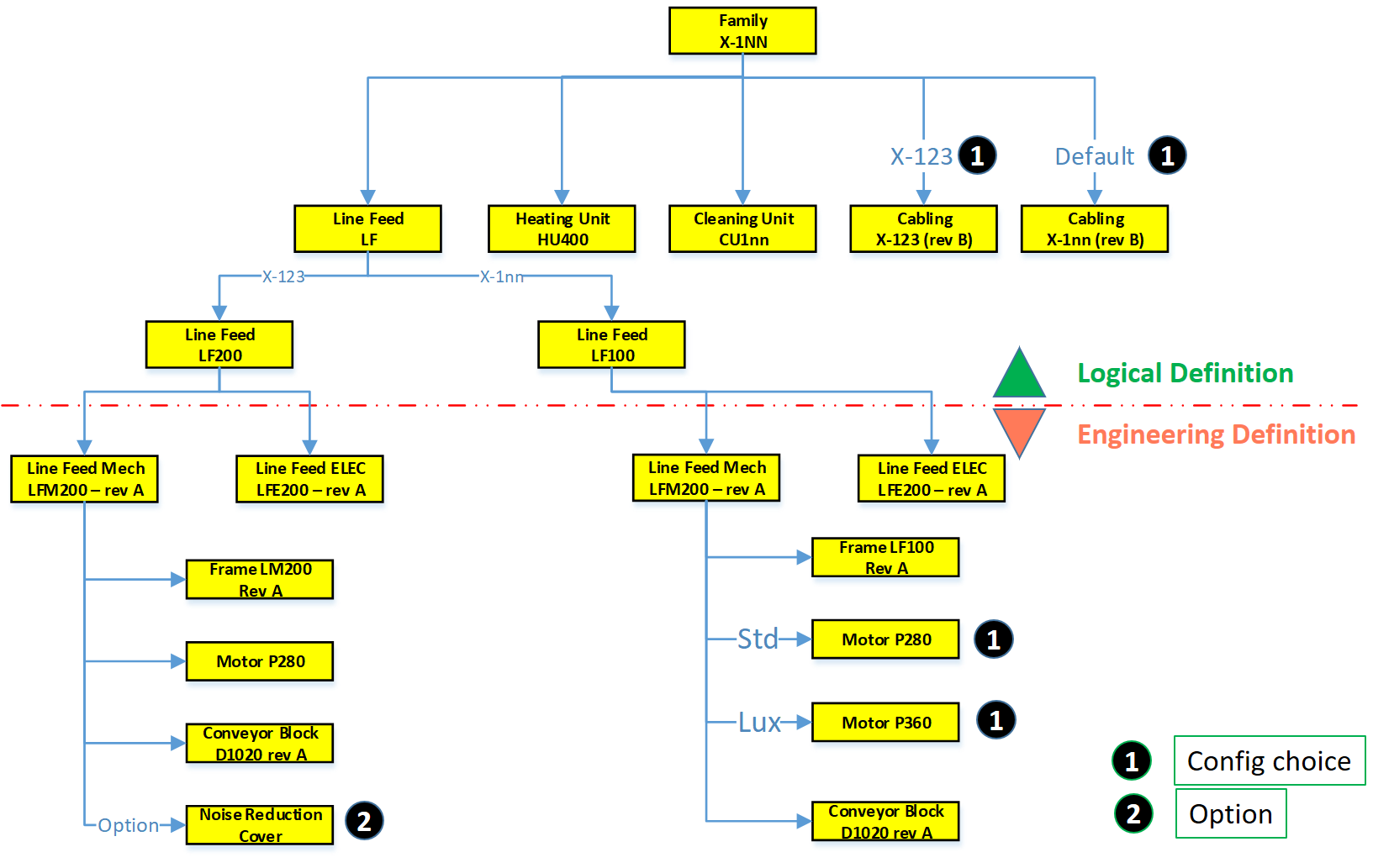
If we look at the diagram, this configured structure contains variants and options.
 First, on the logical definition, we see a new grouping. There are two types of Line Feed available, one specific for the X-123 and a later, more generic designed LF100, suitable for all X-1nn variants.
As the LF100 is more generic designed, the customer can select between two motors, the standard P280 and the more advanced version P360, with better service capabilities.
![]() For the Line Feed LF200, there is an option to order a Noise Reduction Cover. It was sold once to an existing customer, and as the cover fits all X-123, it has been linked here as an option to the X-123 definition. So, the customer solution with the Noise Reduction Cover does not have an isolated, copied structure in the EBOM.
For the Line Feed LF200, there is an option to order a Noise Reduction Cover. It was sold once to an existing customer, and as the cover fits all X-123, it has been linked here as an option to the X-123 definition. So, the customer solution with the Noise Reduction Cover does not have an isolated, copied structure in the EBOM.
Also, in the Logical Structure, we see there is a cabling definition for the X-123 or the default cabling set for all other products.
 The diagram illustrates what many mid-market companies have been doing more or less in their PDM-system to avoid copying of EBOM structures per customer order.
It is an example of where a tool (the PDM-system) is slowly abused for administrative reasons. Let me explain why.
The link between Products and (E)BOMs
If we look at the upper part of the configured EBOM structure, this is a logical product definition. Or to say it in different words, it is a portfolio definition, which products and modules a company can sell to the market. Some of the grouping of the portfolio is purely based on business reasons, which products and options do we want to sell.

In most companies, the product portfolio is managed in (marketing) documents without a direct connection to the engineering world. However, we will see in an upcoming post, this relation is crucial for a digital enterprise. Meanwhile, look at on old blog post: Products, BOMs and Parts if you want to be faster
 The Engineering definition below the red dashed line is a real EBOM, representing the engineering definition of a system, a module, or a component. When these systems and modules are defined in a single structure that can be filtered based on selection criteria, we talk about a Configured EBOM or sometimes a 150 % EBOM.
Each of the components in the configured EBOM can have a related 3D CAD structure or specification that can be developed traditionally.
The result of a resolved EBOM is a variant that can be delivered to the customer. In this EBOM-driven approach, there is not always a full 3D-representation of the customer product.
![]() Again, size (1500+) words make me stop this story, where next time we will go from product to EBOM and introduce the need for an MBOM in specific industries.
Again, size (1500+) words make me stop this story, where next time we will go from product to EBOM and introduce the need for an MBOM in specific industries.
Conclusion
A pure EBOM only specifies a product and contains all relevant information in context – designs & specifications. The EBOM should not be mixed or confused with a logical grouping, belonging to a portfolio definition (even if the system allows you to do it)
On my previous post shared on LinkedIn Ilan Madjar, a long-time PLM colleague reacted with the following point (full thread here)

Ilan is pointing to the right challenge in many companies. Changing the way you work is though exercise and requires a good understanding, vision, and execution to move forward. Do not trust the tool to work for you – it is about human understanding and process re-engineering to be more efficient. And if you do not practice this on the basic PDM-level as discussed so far, imagine the impossibility of going through a digital transformation.
 Last time in the series Learning from the past to understand the future, we zoomed in on how the 3D CAD-structure in the mid-market had to evolve. In a typical Engineering To Order (ETO) scenario, it makes sense to extract from the 3D CAD-structure a BOM-structure to collect all the individual parts that are needed for manufacturing. Combined with the drawings generated based on the 3D CAD assemblies/parts, the complete manufacturing information could be provided. Let’s have a look.
The BOM in ERP (part 1)
To understand what most mid-market companies have been doing, I created the image below. When you click on it, you will have an enlarged version.
Note: for educational purposes an extremely simplified example
There is a lot to explain here.
First, on the right we see the 3D CAD assembly, two phantom assemblies, grouping the wheels and the axle. And at the end, the individual parts, i.e. chassis, axle, and wheel. The 3D CAD-structure is an instance-based structure; therefore, there are no quantities in the structure (all quantity 1)
For the individual parts, there are drawings. Also, for the product, we have an assembly drawing. The drawings are essential as we want to have them in the ERP-system for manufacturing.
Finally, the physical parts, now with a different ID than the drawing as we learned this one-to-one relation created a lot of extra work. The physical parts are often called Items or Materials (SAP naming). Unfortunately, for engineering, there is a different meaning behind Materials. Still, SAP’s data model was not built with an engineering mindset.
The physical part structure, which we call the BOM contains quantities. Most PDM-CAD-integrations can filter out phantom assemblies and summarize the parts on the same level
 I am still reluctant to call the Part-structure an EBOM as the design of the product has been mainly focusing on extracting manufacturing information, parts, and drawings.
The BOM in ERP (part 2)
In customized PDM-implementations, some implementers created an interface from the BOM-structure to ERP, so the ERP-system would have the basic definition of the parts and a copy of the relevant drawings.
Now manufacturing could create the manufacturing definition without the need to go into the PDM-system.
Some “clever” – Dick Bourke would say “smart – therefore lazy” – proposed to “draw” also manufacturing entities in the 3D CAD-structure, so the PDM-CAD-interface would automatically deliver manufacturing parts too inside the ERP. In the example below, we added paint for the body and grease needed for the axels.
Although “smart, a new problem was introduced here – the 3D CAD-structure, instance-based, always has quantities 1. The extracted BOM would have rounded numbers when considering design parts. Now the grease comes with an estimate of 0.025 kg, assuming quantities are based on SI-units. We could also add other manufacturing information to this BOM, like 0.3-liter paint. Anyway, the result would look like below:
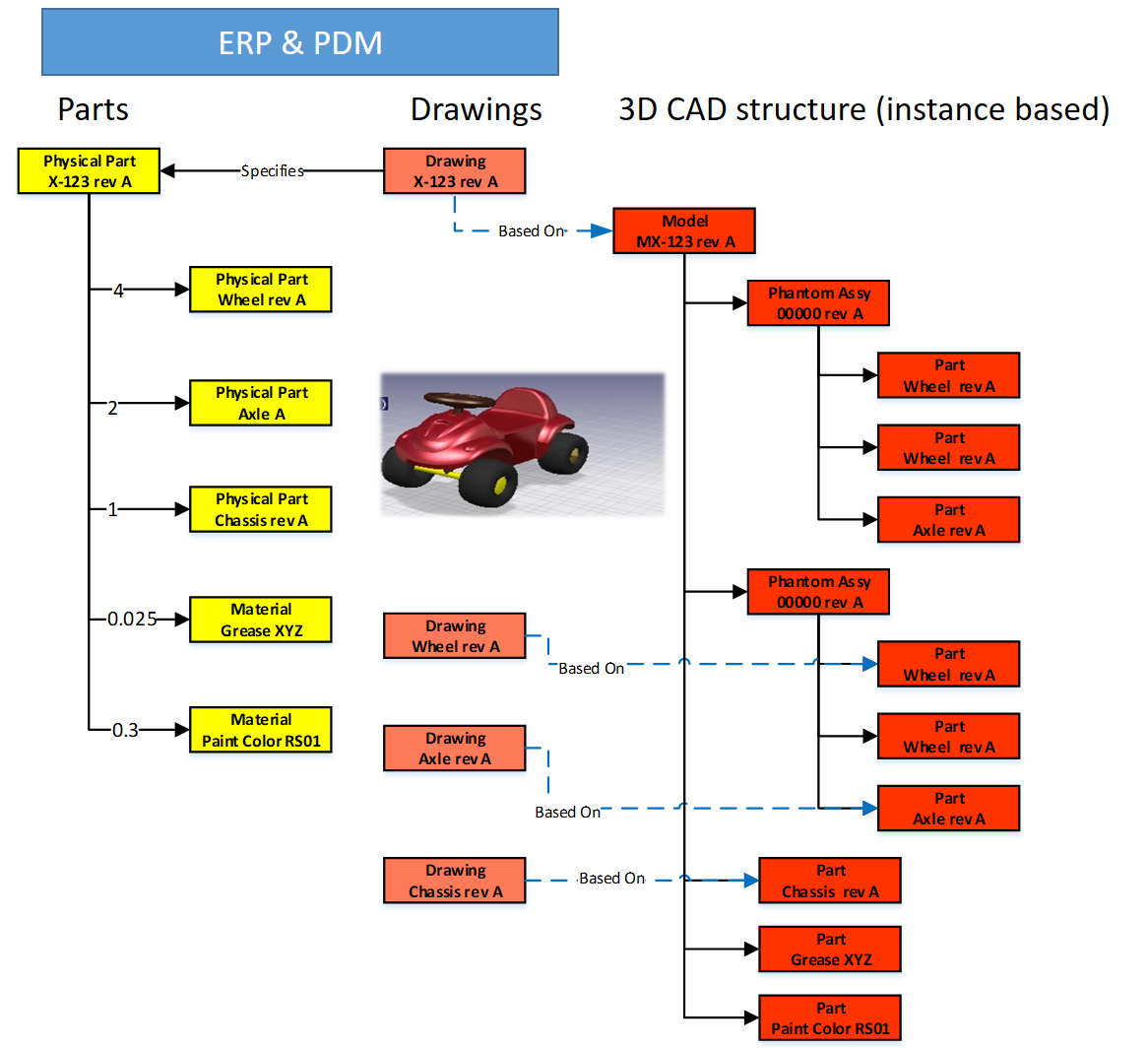
Important to notice from the diagram here: There are placeholders for grease and paint “drawn” in the 3D CAD-structure – parts without a geometrical definition and, therefore, not having an associated drawing. However, these parts have a material specification, and therefore in the BOM-structure, they appear as Materials.
Next in the BOM-structure, the engineers would enter the expected/required quantity – which is no longer a rounded number.
 At this stage, you cannot call the BOM on the left an EBOM. It is a kind of hybrid structure, combining engineering and manufacturing data. A type of BOM we discover a lot in companies that started with a type of ETO-product.
The ETO-product
 Many companies that developed specialized machinery have started with a base product, from where they developed the custom solution – their IP. Next, with more and more customers, the original solution was extended by creating either new or changed capabilities.
I worked a lot with companies that moved to the full definition of their products in 3D CAD, creating a correct 3D CAD-structure per customer order. Instead of creating new BOM variants, companies were often tempted/forced to make the configuration inside the 3D CAD-model.

Every time one of the configurations of the part would change, or a new configuration was added, the file has to be revised.
 And if the change was at level five of a 3D CAD-structure, many assembly files needed to be updated. The versioning problem illustrates the challenge of managing configurations inside a 3D CAD-file, meanwhile creating complexity for the PDM/PLM-system.
Last week Tech-Clarity published the highlights of their survey: Bringing Custom-Engineered Products to Market with a link to the full report, sponsored by Propel.
 As you can imagine, this survey is more about PLM collaboration, breaking down the silos and acting agile. Unfortunately, the report does not expose required methodologies, like modularity and “common sense” engineering practices that we discuss here. Still worthwhile to read as the report addresses precisely the type of companies I am referring too here.
If we look at the methodology of custom-engineered products, let us look at how their “best practice” from the past is blocking the future.
When a new customer request is coming in, sales engineering is looking for the best match of delivered products. Hopefully, 80-90 % remains the same, and engineering has to focus only on the differences.
 First, the best-match 3D CAD-structure is copied to a new project. As you can see most 3D CAD-systems provide the functionality to create a derived structure from an original 3D CAD-structure. From there, a traditional ETO-process starts as described at the beginning of this post. We complete the 3D CAD-structure with manufacturing in mind, generate the BOM and drawings, and we can deliver. In the case of purchase parts, the generated BOM often contains already the supplier part number in the 3D CAD-structure as we are focusing on this single delivery.
The disadvantage of this approach that in theory, we have to check if the structure that we reused is really the best so far, otherwise we introduce errors again.
 The second disadvantage is that if one supplier part in the structure becomes obsolete and needs to be revised, the company has to go through all the 3D CAD-structures to fix it.
Also, having supplier parts in the 3D CAD-structure makes it more difficult to standardize, as the chosen supplier part matched the criteria for that customer at that time. Will it match the criteria also in other situations?
From ETO to BTO to CTO
Many companies that started with custom-engineered products, the ETO-approach, want to move towards a Configure To Order (CTO) approach – or if not possible at least Build To Order (BTO). More reuse, less risk, instead of creating every time a new solution for the next customer, as discussed before.
This is not a mission impossible; however, often, I have seen that companies do not set the right priorities to move towards a configure to order environment. There are a few changes needed to become a configure to order company (if possible):
- Analyze your solution and define modules and options. Instead of defining a full solution, the target now is to discover a commonality between the various solutions. Based on commonality, define modules and options in such a manner that they can be used in different situations. Crucial for these modules is that there is a standard interface to the rest of the product. Every company needs to master this specific methodology for their products
- Start defining products from a logical structure, defining how products, modules and options are compatible and which combinations are allowed (or preferred). For companies that are not familiar with logical structure, often a configured EBOM is used to define the solutions. Not the optimal way; however, this was the first approach most companies took ten years ago. I will explain the configured EBOM below.
- A product definition and its modules now should start from a real EBOM, not containing manufacturing characteristics. The EBOM should represent the logical manner of how a product is defined. You will notice this type of EBOM might be only 2 – 3 levels deep. At the lowest level, you have the modules that have their own lifecycle and isolated definition.
- You should no longer use supplier part numbers in your EBOMs. As the engineering definition of a module or option should not depend over time from a single supplier. We will discuss in the next post the relation between EBOM parts and the Approved Manufacturer List (AML)
To conclude for today
Changing from ETO to CTO requires modularity and a BOM-driven approach. Starting from a 3D CAD-structure can still be done for the lowest levels – the modules, the options. In a configure to order process, it might not be relevant anymore to create a full 3D-representation of the product.
However, when we look forward, it would be greatly beneficial to have the 3D-representation of every specific solution delivered. This is where concepts as augmented/virtual reality and digital twin come in.
Next time more on the BOM-structures – as we have just touched the upcoming of the EBOM – enough to clarify next week(s).
 To understand our legacy in the PLM-domain, what are the types of practices we created, I started this series of posts: Learning from the past to understand the future. My first post (The evolution of the BOM) focused on the disconnected world between engineering – generation of drawings as a deliverable – and execution MRP/ERP – the first serious IT-systems in a company.
At that time, due to minimal connectivity, small and medium-sized companies had, most of the time, an informal connection between engineering and manufacturing. I remember a statement at that time, PLM was just introduced. One person during a conference claimed:
“You guys make our lives so difficult with your systems. If we have a problem, we gather around the machine, and we fix it.”
PLM started at large enterprises
Of course, large enterprises could not afford such behavior as they operate globally. The leading enterprises for PDM/PLM were the Aerospace & Defense and Automotive companies. They needed consistent processes and formal ways of working to guarantee quality output.
 In that sense, I was happy with the reaction from Jean-Jacques Urban-Galindo, who shared in the LinkedIn comments a reference to a relevant chapter of John Stark’s PLM book. In the pdf describing the evolution of CAD / PDM / PLM at PSA. Jean-Jacques was responsible at that time for Responsible for the re-engineering of the Product & Process Engineering processes using digital tools (CAD/CAM, DMU, and more).
Read the PSA story here: PLM at GROUPE PSA. It describes nicely where 3D CAD and EBOM are coming in. In large enterprise like PSA, the need for tools are driven by the processes. When you read it to the end, you will also see the need for a design and a manufacturing view. A topic I will touch in future posts too.
The introduction of 3D CAD in the mid-market
 Where large automotive and aerospace companies already invested in (expensive) 3D CAD hard and software, for the majority of the midsize companies, the switch from 2D CAD (AutoCAD mainly) towards 3D CAD (SolidWorks, Solid Edge, Inventor) started at the end of the 20th century.
It was the time that Microsoft NT became a serious platform beside the existing mainframe and mini-computer based CAD-systems. The switch to PCs went so fast that the disruption from DEC (Digital Equipment Company) is one of the cases discussed by Clayton Christensen in his groundbreaking book: The Innovator’s dilemma
 3D CAD introduced a lot of new capabilities, like DMU (Digital Mock-Up), for clash detection, and above all, a better understanding of a product’s behavior. The introduction of 3D CAD introduced a new set of challenges to be resolved.
For example, the concept of reusing 3D CAD parts. Mid-market companies, most of the time, are buying productivity tools. Can I design my product faster and with higher quality in 3D instead of using only the 2D definitions?
Mid-market companies usually do not redesign their business processes – no people available for strategy – the pain of lack of strategy is felt in a different way compared to large enterprises—a crucial differentiator for the future of PLM.
Reuse of (3D) CAD parts / Assemblies
 In the 2D CAD world, there was not so much reuse of CAD parts. Standard parts were saved in libraries or generated on demand by parametric libraries. Now with 3D CAD, designers might spend more time to define the part. The benefits come from the reuse of small sub-assemblies (modules) into a larger product assembly. Something not relevant in the 2D CAD world.
 As every 3D CAD part had to have a file name, it became difficult to manage the file names without a system. How do you secure that the file with name Part01.xxx is unique? Another designer might also create an assembly, where the 3D CAD tool would suggest Part01.xxx as the name. And what about revisions? Do you store them in the filename, and how do you know you have the correct and latest version of the file?
Companies had already part naming rules for drawings, often related to the part’s usage similar to “intelligent” numbers I mentioned in my previous post.
With 3D CAD it became a little more complicated as now in electronic formats, companies wanted to maintain the relation:
Drawing ID = Part ID = File Name
The need for a PDM-system,
If you look to the image on the left, which I found in one of my old SmarTeam files, there is a part number combined with additional flags A-A-C, which also have meaning (I don’t know ☹ ) and a description.
The purpose of these meaningful flags was to maintain the current ways of working. Without a PDM-system, parts of the assembly could be shared with an OEM or a supplier. File-based 3D CAD without using a PDM-system was not a problem for small and medium enterprises.
The 3D CAD-system maintained the relations in the assembly files, including relations to the 2D Drawings. Despite the introduction of 3D CAD, the 2D Drawing remained the deliverable the rest of the company or supply chain, was waiting for. Preferably a drawing containing a parts list and balloon numbers, the same as it has been done before. Why would you need a PDM-system?
PDM for traceability and reuse
 If you were working in your 3D CAD-system for a single product, or on individual projects for OEMs, there was no significant benefit for a PDM-system. All deliveries needed for the engineering department were in the 3D CAD environment. Assembly files and drawing files are already like small databases, containing references to the source files of the part (image above).
A PDM-system at this stage could help you build traceability and prevent people from overwriting files. The ROI for this part only depends on the cost and risks of making mistakes.
However, when companies started to reuse parts or subassemblies, there was a need for a system that could manage the 3D models separately. This had an impact on the design methodology.
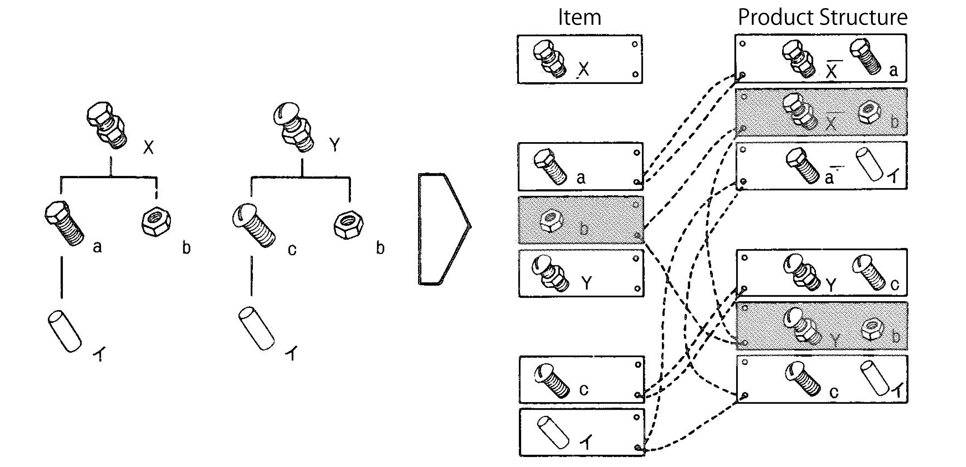 Now parts could be used in various products. How do you discover parts for reuse, and how do you know you have the last released version. For sure their naming cannot be related anymore to a single product or project (a practice still used a lot)
This is where PDM-systems came in. Using additional attributes per file combined with relations between parts, allowing companies to structure and deliver more details related to a part. A detailed description for internal usage, a part type (classification), and the part material were commonly used attributes. And not to forget the status and revision.
For reuse, it was important that the creators of content had a strategy to define a part for future reuse or discovery. Engineerings were not used to provide such services, filling in data in a PDM-system was seen as an overhead – bureaucracy.
As they were measured on the number of drawings they produced, why do extra work with no immediate benefits?
The best compromise was to have the designer fill in properties in the CAD-file when creating a part. Using the CAD-integration with the PDM-system could be used to fill attributes in the PDM-system.
This “beautiful” simple concept lead later to a lot of complexity.
Is the CAD-model the source of data, meaning designers should always start from CAD when designing a product. If someone added or modified data in the PDM-system, should we open the CAD-file to update some properties? Changing a file means it is a new version. What happens if the CAD-file is released, and I update some connected attributes in PDM?
 To summarize this topic. Companies have missed the opportunity here to implement data governance. However, none of the silos (manufacturing preparation, service) recognized the need. Implementing new tools (3D CAD and PDM) did not affect the company’s way of working.
Instead of people, processes, tools, the only focus was on new tools and satisfying the people withing the same process.
 Of course, when introducing PDM, which happened for mid-market companies at the beginning of this century, there was no PLM vision. Talking about lifecycle support was a waste of time for management. As we will discover in the future posts, large enterprises and small and medium enterprises have the same PLM needs. However, there is already a fundamentally different starting point. Where large enterprises are analyzing and designing business processes, the small and medium enterprises are buying tools to improve the current ways of working
The Future?
 Although we have many steps to take in the upcoming posts, I want to raise your attention to an initiative from the PLM Interest Group together with Xlifecycle.com. The discussion is about what will be PLM’s role in digital transformation.
As you might have noticed, there are people saying the word PLM is no longer covering the right context, and all kinds of alternatives have been suggested. I recommend giving your opinion without my personal guidance. Feel free to answer the questionnaire, and we will be all looking forward to the results.
Find the survey here: Towards a digital future: the evolving role of PLM in the future digital world
Conclusion
We are going slow. Discovering here in this post the split in strategy between large enterprises (process focus) and small and medium enterprises (tool focus) when introducing 3D CAD. This different focus, at this time for PDM, is one of the reasons why vendors are creating functions and features that require methodology solving – however, who will provide the methodology.
Next time more on 3D CAD structures and EBOM
In my series of blog posts related to the (PLM) data model, I talked about Product, BOMs and Parts. This time I want to focus on the EBOM and (CAD) Documents relation. This topic became relevant with the introduction of 3D CAD.
Before companies were using 3D CAD systems, there was no discussion about EBOM or MBOM (to my knowledge). Engineering was producing drawings for manufacturing and not every company was using the mono-system (for each individual part a specifying drawing). Drawings were mainly made to assist production and making a drawing for an individual part was a waste of engineering time. Parametric drawings were used to specify similar parts. But now we are in the world of 3D!
 With the introduction of 3D CAD systems for the mainstream in the nineties (SolidWorks, Solid Edge, Inventor) there came a need for PDM systems managing the individual files from a CAD assembly. The PDM system was necessary to manage all the file versions. Companies that were designing simple products sometimes remained working file-based, introducing the complexity of how to name a file and how to deal with revisions. Ten years ago I was investigating data management for the lower tiers of the automotive supply chain. At that time still 60 % of the suppliers were using CATIA were working file-based. Data management was considered as an extra complexity still file version control was a big pain.
This has changed for several reasons:
- More and more OEMs were pushing for more quality control of the design data (read PDM)
- Products became more modular, which means assemblies can be used as subassemblies in other products, pushing the need for where used control
- Products are becoming more complex and managing only mechanical CAD files is not enough anymore – Electronics & Software – mechatronics – became part of the product
Most PDM systems at that time (I worked with SmarTeam) were saving the 3D CAD structure as a quantity-based document structure, resembling a lot a structure called the EBOM.

This is one of the most common mistakes made in PLM implementations.
The CAD structure does not represent the EBOM !!!
Implementers started to build all kind of customizations to create automatically from the CAD structure a Part structure, the EBOM. Usually these customizations ended up as a mission impossible, in particular when customers started to ask for bidirectional synchronization. They expected that when a Part is removed in the EBOM, it would be deleted in the CAD assembly too.
And then there was the issue that companies believed the CAD Part ID should be equal to the Part ID. This might be possible for a particular type of design parts, but does not function anymore with flexible parts, such as a tube or a spring. When this Part is modeled in a different position, it created a different CAD Document, breaking the one-to-one relation.
Finally another common mistake that I have seen in many PDM implementations is the addition of glue, paint and other manufacturing type of parts to the CAD model, to be able to generate a BOM directly from the CAD.
 From the data model perspective it is more important to understand that Parts and CAD documents are different type of objects. In particular if you want to build a PLM implementation where data is shared across all disciplines. For a PDM implementation I care less about the data model as the implementation is often not targeting enterprise continuity of data but only engineering needs.
A CAD Document (Assembly / Part / Drawing / …) behaves like a Document. It can be checked-in and checked out any time a change is made inside the file. A check-in operation would create a new version of the CAD Document (in case you want to trace the history of changes).
Meanwhile the Part specified by the CAD Document does not change in version when the CAD Document is changed. Parts usually do not have versions; they remain in the same revision as long as the specifying CAD Document matures.
Moving from PDM to PLM
For a PLM implementation it is important to think “Part-driven” which means from an initial EBOM, representing the engineering specification of the Product, maturing the EBOM with more and more design specification data. Design specification data can be mechanical assemblies and parts, but also electrical parts. The EBOM from a PCB might come from the Electrical Design Application as in the mechanical model you will not create every component in 3D.
And once the Electrical components are part of the EBOM, also the part definition of embedded software can be added to the BOM. For example if software is needed uploaded in flash memory chips. By adding electrical and software components to the EBOM, the company gets a full overview of the design maturity of ALL disciplines involved.
The diagram below shows how an EBOM and its related Documents could look like:

This data model contains a lot of details:
- As discussed in my previous post – for the outside world (the customer) there is a product defined without revision
- Related to the Product there is an EBOM (Part assembly) simplified as a housing (a mechanical assembly), a connector (a mechanical art) and a PCB (a mechanical representation). All these parts behave like Mechanical Parts; they have a revision and status.
- The PCB has a second representation based on an electrical schema, which has only (for simplification) two electrical parts, a resistor and a memory chip. As you can see these components are standard purchasable parts, they do not have a revision as they are not designed.
- The Electrical Part Flash Memory has a relation to a Software Part which is defined by Object Code (a zip-file?) which of course is specified by a software specification (not in the diagram). The software object code has a version, as most of the time software is version managed, as it does not follow the classical rules of mechanical design.
Again I reached my 1000 words, a sign to stop explaining this topic. For sure there are a lot of details to explain to this data model part too.
Most important:
- A CAD structure is not an EBOM (it can be used to generate a part of the EBOM)
- CAD documents and EBOM parts have a different behavior. CAD documents have versions, Parts do not have versions (most of the time
- The EBOM is the place where all disciplines synchronize their data, providing during the development phase a single view of the design status.
Let me know if this was to abstract and feel free to ask questions. Important for this series of blog post is to provide a methodology baseline for a real PLM data model.
I am looking forward to your questions or remarks to spark up the discussion.

First of all happy new year to all of you. As there is no “End of the World” risk anymore in the near future , we can start looking forward and set our goals for the next 5 years or is it a 7-years plan Oleg ?.
Christmas, the moment the light returns on the Northern hemisphere, plus the food , cycling and the preparations for the next Product Innovation conference in Berlin were the drivers for this blog post.
The title might give you the impression that it is an IQ-quiz: “Which word does not fit in this sequence”? Well, It’s not, they are all related. Let’s put them in a chronological order.
Frogs
 Frogs existed first, and were exploring the world before us humans. Paleontologists assume they had no notion of what was global. In their world it was probably a few ponds in size. For certain, they did not have anything to do with innovation. At that time, survival depended on the slow process of evolution.
Millions of years later, the first Homos appeared on the earth surface; Homo Sapiens, Homo Erectus, Homo Ludens and perhaps more. They all had something in common: Instead of waiting for the evolution which was ongoing, they started in parallel to innovate. First by walking upright, using a more advanced language to communicate and learning to have tools to achieve more. Their world was still within a reasonable walking distance and probably they started to eat frogs.
Human evolution
 This evolution continued for thousands of years. Human beings started to spread around the world and in waves they brought innovation. They built stone temples, learned to sail, discovered gunpowder, electricity, the universe, the internet and more. It is interesting to see that every time a major innovation was born, these innovators enriched their region in wealth and culture, using their innovation as a competitive advantage to dominate their neighbors.
In many cases 1000 years later, this innovation became a commodity and other civilizations stood up with their innovation and dominated their regional environment which became bigger and bigger in size. Where possible they made use of the cheap resources (modern word for what was initially called slaves) to enrich their civilization. For certain, the most civilized were eating frogs!
Market expansion – innovation pace
During the last century, the pace of innovation went faster and faster. New ways of communication and transportation became available and affordable, which made it impossible for innovations to stay within a specific civilization. Innovation became available for everyone around the world and the domination shifted towards companies and markets.
 Companies with a strategy to innovate, discovered that there were new ways needed to respond faster than before to market opportunities. This was the driving force behind PDM, as an first attempt to get a better grip and understanding of their fast evolving, more complex products, that require more and more global collaboration between design teams.
PDM is now accepted as critical by all manufacturing companies around the world, to guarantee quality and efficiency. Customer focus became the next demand from the market and interestingly enough, the demand for frogs decreased.
However this wave of innovation was followed by a wave with even greater impact on the global society. New technologies, the availability of internet and social media, suddenly changed society. Combined with the financial crisis in the US and Europe, it became clear that the way we worked in the past is no longer the way to survive in the future.
Faster and global
 PLM was introduced early this century as a new strategy to become more customer-centric, being able to respond faster and better to market demands by bringing innovation to the market before the competition. PLM requires a different approach by companies to work internally and interact with the (global) outside world. The need to implement the PLM vision requires change and as it cannot be considered as an evolutionary process over several generations, it will be a business change. However, in general, human beings do not like rapid change. Here the frogs come back into the picture, now as the boiling frog metaphor.
It is based on 19th century anecdote describing a frog slowly being boiled alive. The premise is that if a frog is placed in boiling water, it will jump out, but if it is placed in cold water that is slowly heated, it will not perceive the danger and will be cooked to death. The story is often used as a metaphor for the inability of people to react to significant changes that occur gradually. This metaphor is very applicable for the classical approach companies bring their products to the market, where innovation is more a lucky coincidence than a result of a strategy.
Here it all comes together again.
 Innovation is the only way for companies to avoid becoming a commodity – not able to differentiate for your potential customers. Now the title of this post should be clear: “Do not be a boiling frog, use PLM to support your innovation and become available for the global market”
As the new year has started and it is still time to extend your good intentions, add Innovation, PLM and Change to your survival list.
I look forward to your comments and hope to discuss with you the relation between PLM and Innovation during the upcoming Product Innovation event in Berlin, where I present a session with the title: “PLM loves Innovation ?”
(when you know me, you know the answer, but there are always surprises)

Related articles
- Are we as dumb as “Slowly Boiling Brainless Frogs”? (1) (blogs.redding.com)

Hi Jos, Knowing your background in methodology and education, I wanted to share a longer article with you: “What is…
Interesting reflection, Jos. In my experience, the situation you describe is very recognizable. At the company where I work, sustainability…
[…] (The following post from PLM Green Global Alliance cofounder Jos Voskuil first appeared in his European PLM-focused blog HERE.) […]
[…] recent discussions in the PLM ecosystem, including PSC Transition Technologies (EcoPLM), CIMPA PLM services (LCA), and the Design for…
Jos, all interesting and relevant. There are additional elements to be mentioned and Ontologies seem to be one of the…