
You are currently browsing the tag archive for the ‘CAD’ tag.
 Last time in the series Learning from the past to understand the future, we zoomed in on how the 3D CAD-structure in the mid-market had to evolve. In a typical Engineering To Order (ETO) scenario, it makes sense to extract from the 3D CAD-structure a BOM-structure to collect all the individual parts that are needed for manufacturing. Combined with the drawings generated based on the 3D CAD assemblies/parts, the complete manufacturing information could be provided. Let’s have a look.
The BOM in ERP (part 1)
To understand what most mid-market companies have been doing, I created the image below. When you click on it, you will have an enlarged version.
Note: for educational purposes an extremely simplified example
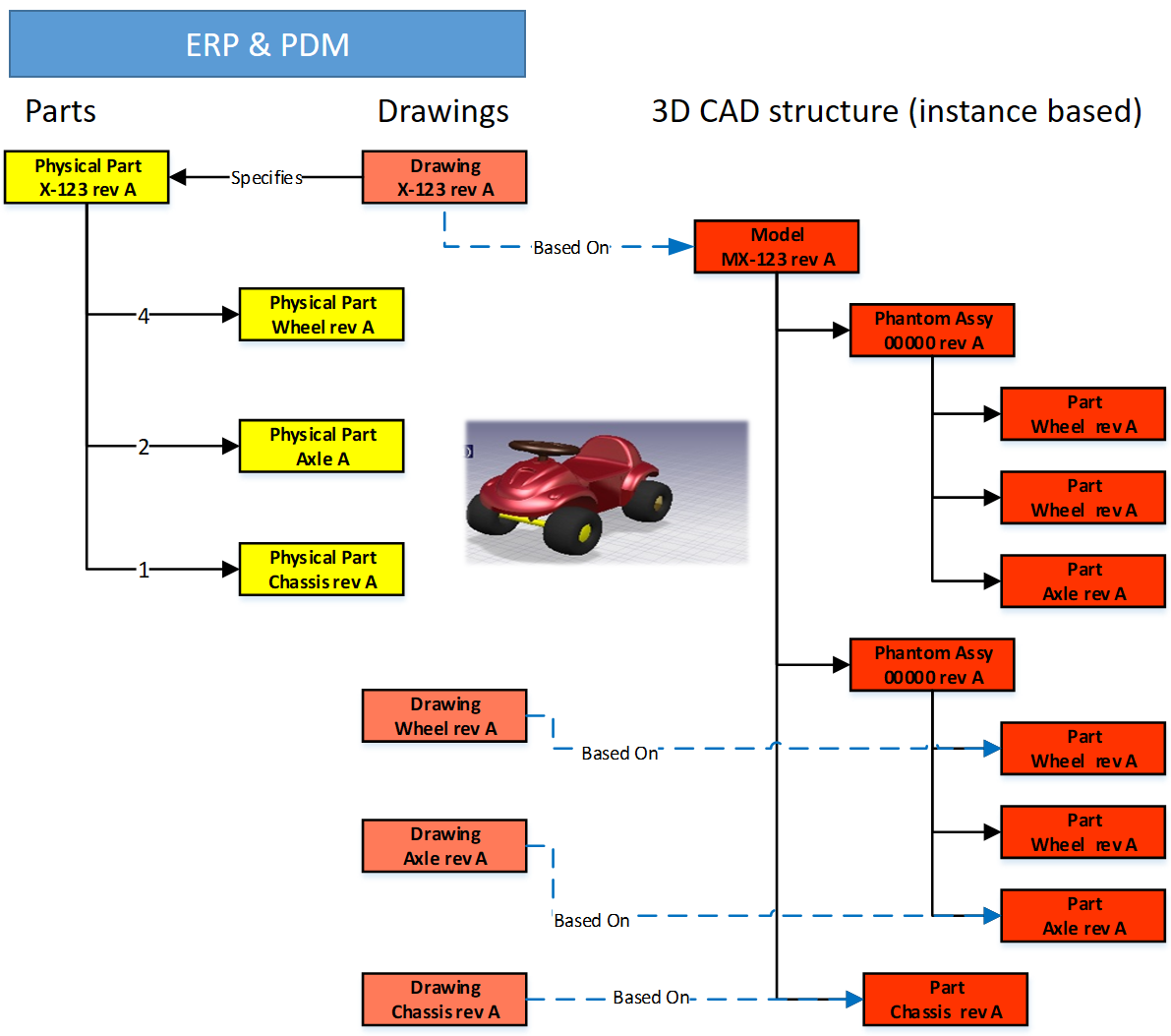
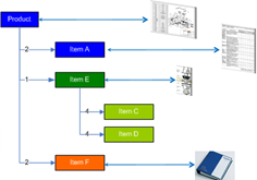
There is a lot to explain here.
First, on the right we see the 3D CAD assembly, two phantom assemblies, grouping the wheels and the axle. And at the end, the individual parts, i.e. chassis, axle, and wheel. The 3D CAD-structure is an instance-based structure; therefore, there are no quantities in the structure (all quantity 1)
For the individual parts, there are drawings. Also, for the product, we have an assembly drawing. The drawings are essential as we want to have them in the ERP-system for manufacturing.
Finally, the physical parts, now with a different ID than the drawing as we learned this one-to-one relation created a lot of extra work. The physical parts are often called Items or Materials (SAP naming). Unfortunately, for engineering, there is a different meaning behind Materials. Still, SAP’s data model was not built with an engineering mindset.
The physical part structure, which we call the BOM contains quantities. Most PDM-CAD-integrations can filter out phantom assemblies and summarize the parts on the same level
 I am still reluctant to call the Part-structure an EBOM as the design of the product has been mainly focusing on extracting manufacturing information, parts, and drawings.
The BOM in ERP (part 2)
In customized PDM-implementations, some implementers created an interface from the BOM-structure to ERP, so the ERP-system would have the basic definition of the parts and a copy of the relevant drawings.
Now manufacturing could create the manufacturing definition without the need to go into the PDM-system.
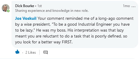
Some “clever” – Dick Bourke would say “smart – therefore lazy” – proposed to “draw” also manufacturing entities in the 3D CAD-structure, so the PDM-CAD-interface would automatically deliver manufacturing parts too inside the ERP. In the example below, we added paint for the body and grease needed for the axels.
Although “smart, a new problem was introduced here – the 3D CAD-structure, instance-based, always has quantities 1. The extracted BOM would have rounded numbers when considering design parts. Now the grease comes with an estimate of 0.025 kg, assuming quantities are based on SI-units. We could also add other manufacturing information to this BOM, like 0.3-liter paint. Anyway, the result would look like below:
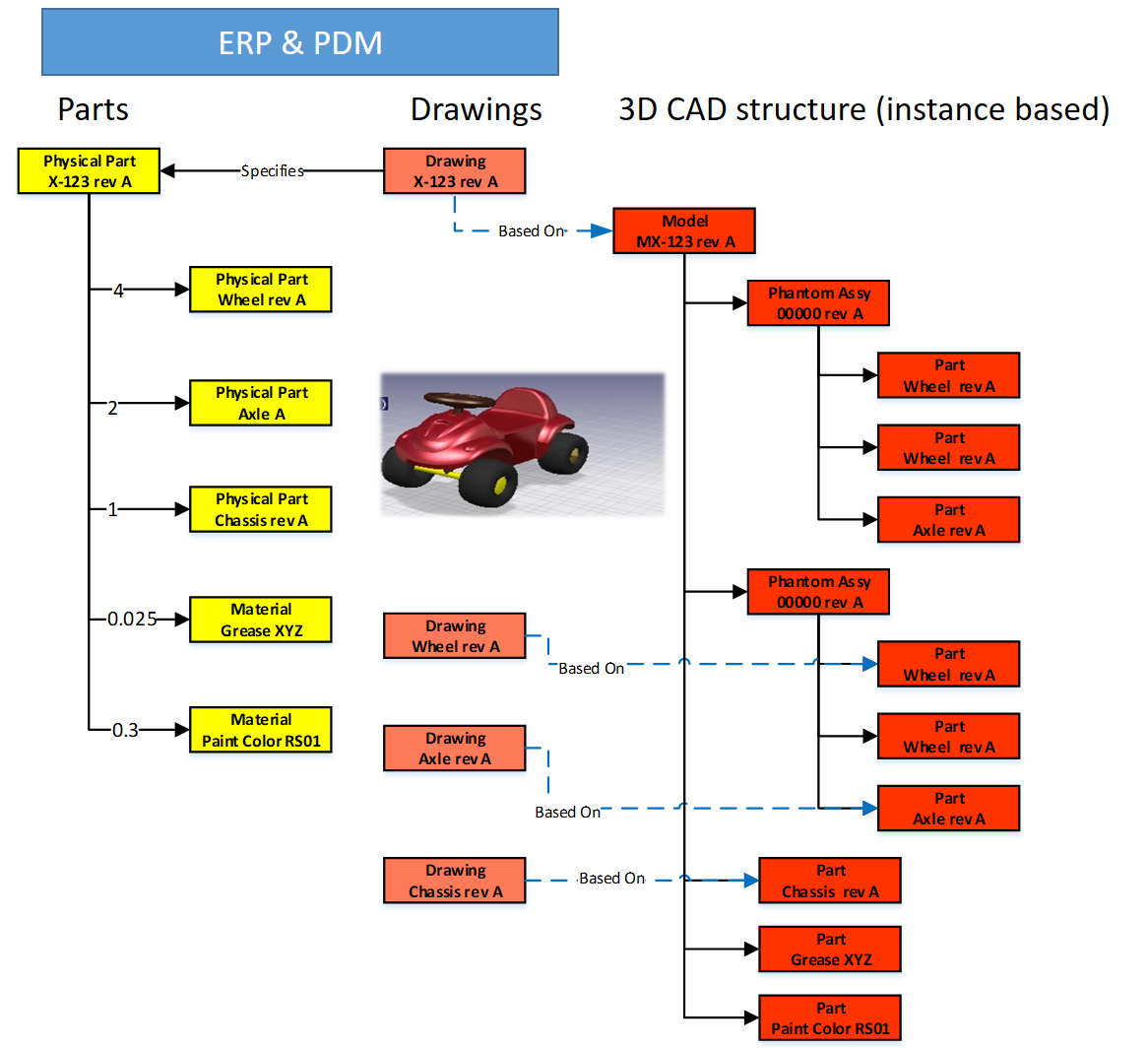
Important to notice from the diagram here: There are placeholders for grease and paint “drawn” in the 3D CAD-structure – parts without a geometrical definition and, therefore, not having an associated drawing. However, these parts have a material specification, and therefore in the BOM-structure, they appear as Materials.
Next in the BOM-structure, the engineers would enter the expected/required quantity – which is no longer a rounded number.
 At this stage, you cannot call the BOM on the left an EBOM. It is a kind of hybrid structure, combining engineering and manufacturing data. A type of BOM we discover a lot in companies that started with a type of ETO-product.
The ETO-product
 Many companies that developed specialized machinery have started with a base product, from where they developed the custom solution – their IP. Next, with more and more customers, the original solution was extended by creating either new or changed capabilities.
I worked a lot with companies that moved to the full definition of their products in 3D CAD, creating a correct 3D CAD-structure per customer order. Instead of creating new BOM variants, companies were often tempted/forced to make the configuration inside the 3D CAD-model.

Every time one of the configurations of the part would change, or a new configuration was added, the file has to be revised.
 And if the change was at level five of a 3D CAD-structure, many assembly files needed to be updated. The versioning problem illustrates the challenge of managing configurations inside a 3D CAD-file, meanwhile creating complexity for the PDM/PLM-system.
Last week Tech-Clarity published the highlights of their survey: Bringing Custom-Engineered Products to Market with a link to the full report, sponsored by Propel.
 As you can imagine, this survey is more about PLM collaboration, breaking down the silos and acting agile. Unfortunately, the report does not expose required methodologies, like modularity and “common sense” engineering practices that we discuss here. Still worthwhile to read as the report addresses precisely the type of companies I am referring too here.
If we look at the methodology of custom-engineered products, let us look at how their “best practice” from the past is blocking the future.
When a new customer request is coming in, sales engineering is looking for the best match of delivered products. Hopefully, 80-90 % remains the same, and engineering has to focus only on the differences.
 First, the best-match 3D CAD-structure is copied to a new project. As you can see most 3D CAD-systems provide the functionality to create a derived structure from an original 3D CAD-structure. From there, a traditional ETO-process starts as described at the beginning of this post. We complete the 3D CAD-structure with manufacturing in mind, generate the BOM and drawings, and we can deliver. In the case of purchase parts, the generated BOM often contains already the supplier part number in the 3D CAD-structure as we are focusing on this single delivery.
The disadvantage of this approach that in theory, we have to check if the structure that we reused is really the best so far, otherwise we introduce errors again.
 The second disadvantage is that if one supplier part in the structure becomes obsolete and needs to be revised, the company has to go through all the 3D CAD-structures to fix it.
Also, having supplier parts in the 3D CAD-structure makes it more difficult to standardize, as the chosen supplier part matched the criteria for that customer at that time. Will it match the criteria also in other situations?
From ETO to BTO to CTO
Many companies that started with custom-engineered products, the ETO-approach, want to move towards a Configure To Order (CTO) approach – or if not possible at least Build To Order (BTO). More reuse, less risk, instead of creating every time a new solution for the next customer, as discussed before.
This is not a mission impossible; however, often, I have seen that companies do not set the right priorities to move towards a configure to order environment. There are a few changes needed to become a configure to order company (if possible):
- Analyze your solution and define modules and options. Instead of defining a full solution, the target now is to discover a commonality between the various solutions. Based on commonality, define modules and options in such a manner that they can be used in different situations. Crucial for these modules is that there is a standard interface to the rest of the product. Every company needs to master this specific methodology for their products
- Start defining products from a logical structure, defining how products, modules and options are compatible and which combinations are allowed (or preferred). For companies that are not familiar with logical structure, often a configured EBOM is used to define the solutions. Not the optimal way; however, this was the first approach most companies took ten years ago. I will explain the configured EBOM below.
- A product definition and its modules now should start from a real EBOM, not containing manufacturing characteristics. The EBOM should represent the logical manner of how a product is defined. You will notice this type of EBOM might be only 2 – 3 levels deep. At the lowest level, you have the modules that have their own lifecycle and isolated definition.
- You should no longer use supplier part numbers in your EBOMs. As the engineering definition of a module or option should not depend over time from a single supplier. We will discuss in the next post the relation between EBOM parts and the Approved Manufacturer List (AML)
To conclude for today
Changing from ETO to CTO requires modularity and a BOM-driven approach. Starting from a 3D CAD-structure can still be done for the lowest levels – the modules, the options. In a configure to order process, it might not be relevant anymore to create a full 3D-representation of the product.
However, when we look forward, it would be greatly beneficial to have the 3D-representation of every specific solution delivered. This is where concepts as augmented/virtual reality and digital twin come in.
Next time more on the BOM-structures – as we have just touched the upcoming of the EBOM – enough to clarify next week(s).
 In my last post, My four picks from PLMIF, I ended with the remark that the discussion related to the Multiview BOM concept was not complete. The session presented by James Roche focused on the Aerospace & defense domain and touched the surface. There is a lot of confusion related to best practices associated with BOM-handling. Sometimes created to promote unique vendor capabilities or to hide system complexity.
Besides, we need to consider the past as, in particular, for PLM, the burden of legacy processes and data is significant. Some practices even come from the previous, paper-based century, later mixed with behavior from 3D CAD-systems.
 Therefore, to understand the future, I will take you through the past to understand why certain practices were established. Next, in a few upcoming posts, I want to explain the evolution of BOM-practices. How each new technology step introduced new capabilities that enabled companies to improve their product delivery process.
I will describe the drawing approach (for PLM – the past), the item-centric approach (for PLM – the current), and the model-driven approach(for PLM – the future). How big this sequence will become is not clear at this stage.
 Whenever I come close to 1200 – 1500 words, I will stop and conclude. Based on my To-do list and your remarks, I will continue in a follow-up post. The target will be to have a vendor-neutral collection of information to help you identify your business and the next possible steps.
Working with drawings

MRP/ERP – the first IT-system
For this approach, I go back fifty years in time, when companies were starting to work with their first significant IT-system, the MRP-system. MRP stands for Material Requirements Planning. This system became the heart of the company, scheduling the production. The extension to ERP (Enterprise Resource Planning) quickly after, made it possible to schedule other resources and, essential for the management, to report financials. Now execution could be monitored by generating all kinds of reports.
Still, the MRP/ERP-system was wholly disconnected from the engineering world as the image shows below. Let us have a look at how this worked at that time.

The concept
 Products have never been designed from scratch by jumping to drawings. In the concept phase, a product was analyzed, mainly on its mechanical behavior. Was there anything else at that time? Many companies thank their existence from a launching product which someone, most of the time, the founder of the company, invented in a workshop. The company than improved and enriched this product by starting from the core product, creating enhancements in various areas of applicability.
These new ideas were shared through sketches and prototypes.
The design
The detail design of a product is delivered by a technical documentation set, often a package of manufacturing drawings containing a list of parts on the drawing, assembly with instructions. Balloon numbers are used to indicate parts in an assembly or section view. In addition, there are the related fabrication drawings. The challenge for this approach is that all definitions must be there uniquely and complete to avoid ambiguity, which could lead to manufacturing errors.
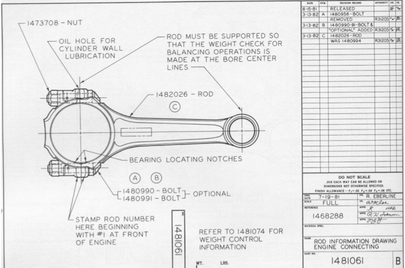
The parts list contains make-parts, supplier parts, and standard parts. The make-parts are specified again by manufacturing drawings, identified by a number that uniquely identifies the correct drawing version. A habit here: Part number = Drawing Number (+ revision)
![]() As the part is identified by a drawing the part most of the time got an “intelligent” part number and a revision. Intelligent to support easy recognition and revisions as at the end we do not want to generate a new part number when there is an evolution of the part. Read more about this in What the FFF is happening and “Intelligent” part numbers?
As the part is identified by a drawing the part most of the time got an “intelligent” part number and a revision. Intelligent to support easy recognition and revisions as at the end we do not want to generate a new part number when there is an evolution of the part. Read more about this in What the FFF is happening and “Intelligent” part numbers?
 The standardized parts can be either company standard parts or external standard parts. There is a difference between them.
A company standard part could be a certain bracket, a frame. Anything that the company decided to standardize on for its own products Company standard parts are treated like make parts; they have an identifier related to their manufacturing drawings. Again, here the habit: Part Number = Drawing Number (+ revision)
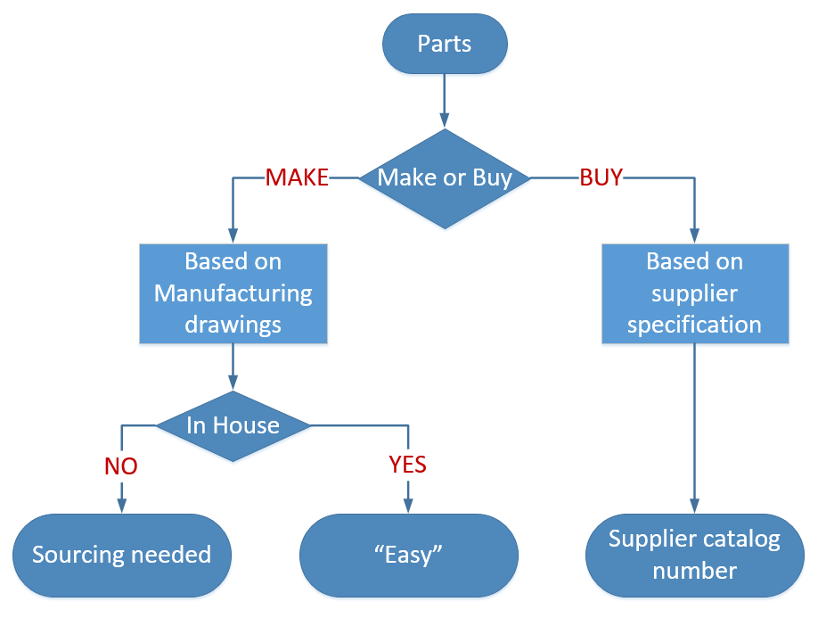
The supplier part is coming from a supplier that manufactures this part based on the supplier or market specifications. You can specify this part by using the supplier’s catalog number or refer to the standard.
 For example, the part that has been specified under a certain ISO/ANSI/DIN-standard. For example, a stainless-steel bolt M8 x 1,25 x 20, meaning a metric bolt with a head diameter of 8 mm, a speed of 1,25 mm, and a length of 20 mm. You specify the standard part according to the standard. Purchasing will decide where to buy this part
Manufacturing Preparation
This is the most inefficient stage when working in a traditional drawing approach. At this stage, the information provided in drawings needs to be entered into the MRP/ERP-system to start production. This is the place where information is thrown over the wall as some might say.
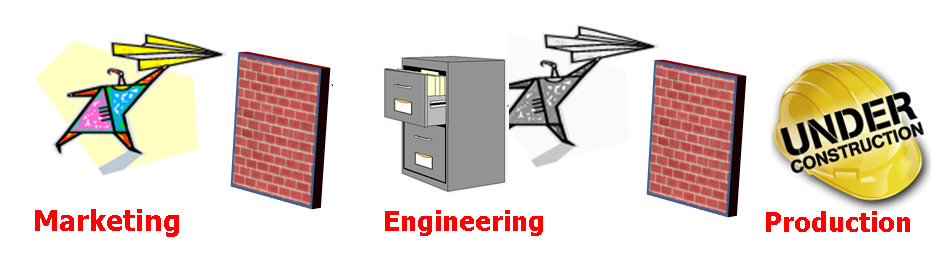
This means a person needs to create process steps in the ERP-system based on the drawing information. For each manufacturing step, there needs to be a reference to the right drawing. Most ERP-systems have a placeholder where you can type the drawing number(s). Later, when companies were using CAD, there could be a reference to a file.
 The part number in the ERP-system might be the same as the drawing number; however, the ERP-system requires unique numbers. In the beginning, ERP-systems were the number-generator for new parts. The unique number was often 6 to 7 digits in size, because it fits in our human short-term memory.
The parts list on the drawings had to be entered in the ERP-system too. A manual operation that often required additional research from the manufacturing engineer. As the designer might have specified the SS Bolt M8 x 1,25 x 20 as such, manufacturing preparation has to search in the ERP-system for the company’s part number.
Suppliers have to be sourced for outside manufactured make-parts. In case you do not want to depend on a single supplier, you have to send drawings and specifications to the supplier before the product is released. The supplier will receive a drawing number with revision and status warning.
If everything worked well the first time, there would be no iterations between engineering and manufacturing preparation. However, this is a utopia: prototype changes, potential manufacturing issues will require changes in the drawings. These changes require updates in the drawings, which will lead to new versions. How do you keep consistency between all identifiers?
Manufacturing
 During manufacturing, orders are processed based on information from the ERP-system. The shop floor gets the drawing provided to the link in ERP. Sometimes there are issues during manufacturing. In coordination with engineering, some adaptations will be made to the manufacturing process. e.g., a changed fit or tolerance. Instead of going back to engineering to provide a new documentation set, the relevant drawings are redlined. Engineering will update these drawings whenever they touch them in the future (yeah, yeah).
Configuration Management
But will they update them? Perhaps already a new version existed due to the product’s evolution. Everything needs to be coordinated manually. Smaller companies heavily rely on people knowing things and talking together.
Larger companies cannot work in the same manner; therefore, they introduce procedures to guarantee that the information flow is consistent and accurate. Here the practices from configuration management come in.
 There are many flavors of configuration management. Formal CM was first used in the 1950s to control the technical documentation for complex space and weapons systems. (Source ESA CM initiative for SME’s – © 2000) We will see it come back in future posts dealing with more complex products and the usage of computer systems.
Last year I wrote a few times about PLM and configuration management (PLM and CM – a happy marriage?) not relevant at this moment as there is no PLM yet.
Where is the BOM
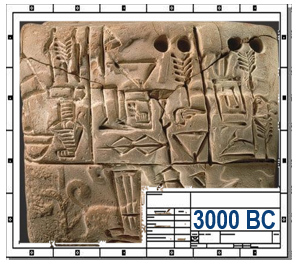
As you might have noticed, there was no mentioning of a BOM so far. At this stage, there is only one Bill of Materials managed in the ERP-system. The source from the BOM comes from the various parts lists on the drawings, completed with manual additions.
 Nobody talks in this stage about an EBOM or MBOM as there is only one BOM, a kind of hybrid BOM, where manufacturing steps were driving the way parts are grouped. Because the information was processed step by step, why would you like to have a multilevel BOM or a BOM tree?
Note: The image on the left was one of my first images in 2008 when I started my blog.
Summary
Working with drawings introduced “intelligent” part numbers as the documents have to be identified by manual interpretations. The intelligence of the part number was there to prevent people from making mistakes as the number already was a kind of functional identifier. Combined with a revision and versioning in the number, nothing could go wrong if handled consistently.
 The disadvantage was that new employees had to master a numbering system. Next, the risk for all employees that a released drawing will not change its status. Only manual actions (retract/replace) will avoid making mistakes. And then, there are the disconnected redline drawings.
The “drawing number equals part number” relation created a constraint that will be hard to maintain in the future. Therefore you should worry if you still work according the above principles.
Conclusion
I reached the 1500 words – a long story – probably far from complete. I encourage readers to provide enhancements that might be relevant in the comments. This post might look like a post for dummies. However, to understand what is applicable to the future, we first need to understand why certain practices have been defined in the past.
I am looking forward to your comments and enhancements to make this a relevant stream of public information for all.
One week ago, Yoann Maingon wrote an innocent post with the question: Has FFF killed? The question was raised related to a 2014 problem at GM, where a changed part was causing fatal accidents.
 The discussion started by Yoann and here my short extract. Assuming this problem was a configuration management issue and Yoann somehow indicated that the problem might be related to the fact that ERP-systems do not carry a revision on the part number – leading to an unnoticed change. Therefore, he assumes there is a disconnect between the PLM-side (where we have parts with multiple lifecycle states and revisions) and ERP (where we have an industrial lifecycle – prototype/production).
He posted his thoughts, and then LinkedIn exploded (currently 116 comments), which means it is a topic that is of significant concern in our community. Next, if you read the comments, there are different viewpoints:
- What does FFF really imply?
- What about revisions of parts?
- What are the best practices?
Let’s investigate these viewpoints with some comments
What does FFF really imply?
When we talk about FFF in engineering, we mean Form, Fit and Function – the three primary characteristics to describe a part (source Wikipedia)
- Form refers to such characteristics as external dimensions, weight, size, and visual appearance of a part or assembly. This is the element of FFF that is most affected by an engineer’s aesthetic choices, including enclosure, chassis, and control panel, that become the outward “face” of the product.
- Fit refers to the ability of the part or feature to connect to, mate with, or join to another feature or part within an assembly. The “fit” allows the part to meet the required assembly tolerances to be useful.
- Function is a criterion that is met when the part performs its stated purpose effectively and reliably. In an electronics product, for example, a function can depend on the solid-state components used, the software or firmware, and quite often on the features of the electronics enclosure selected.
 One of the comments in Yoann’s post referred to Safe/Unsafe as a potential functional characteristic. I think this addition is not needed. Safety should be a requirement for the part, not a characteristic.
FFF was and still is an approach for engineers to decide if a new, improved version of the part would get a revision or needs a new part number.
I think before we dive deeper into the other viewpoints, it is crucial to define the part number a little more.
In a correct PLM data model, there are two types of part numbers. First, the internal part number that your company uses inside its engineering Bill of Materials to identify a part. This part number can be a meaningless part only to provide uniqueness inside the company.
In 2015 I wrote several posts related to best practices and data modeling for PLM. The most relevant posts to this discussion are here:
The part number can specify a part that needs to be manufactured according to specification, or it can be a part that needs to be purchased from an available supplier/manufacturer. The manufacturer part number is, most of the time, a meaningful number (6 – 7 characters) as these parts need to be ordered by your company. The manufacturer part number is the SKU for the manufacturer. As you can imagine in the manufacturer’s catalog, there isn’t a revision mentioned. In graphics, see the image below:

Your company might sell Product MP-323121 (note: the ID is meaningful to help the customer to order the product).
Internally there is a related EBOM that specifies the product. The EBOM top part is O122 (note: here, we can use a meaningless identifier as all is digitally connected).
For the manufacturing of O122, we need to resolve the EBOM according to its specifications. Therefore, for Part O124, the company needs to decide to purchase from their approved manufacturers either part ABC-21231 or XYZ-88818 (note: again, a meaningful ID as these companies are not digitally connected).
Now coming back to the FFF-discussion. For the orange parts, with a meaningful ID, no revision exists. However, if Assembly O122 is 100% FFF compatible, the Product ID MP-323121 will not change. It allows your company to optimize the EBOM and/or MBOM, meanwhile keeping 100% compatibility to the outside world. (note: the same principle applies to the two manufacturers for Part O124.)
In case Top Assembly O122 has new or changed parts – what should happen there?
 At that moment, the definition has changed. The definitions, most of the time described in documents/drawings/models, are related information to the BOM. Therefore the Top Assembly O122 should get a new identifier. There is no need to name it a revision, it is a new data set in the PLM-system, again with a meaningless identifier as we are connected digitally,
What about revisions of parts?
Of course, the management of changes existed long before PLM-systems were introduced.
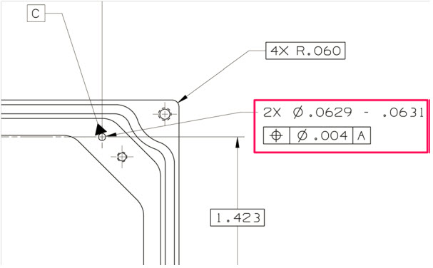
 The specifications of a part were defined in drawings. The drawing contained all the information, not only the geometry definitions, but also specifications on how to manufacture the part.
For complex products, a considerable set of consistently related drawings would be released to manufacturing. A release process with physical signatures on it.
At the same time, there was no discussion: the drawing represents the part. And as there was no digital connection, part numbers/drawing numbers were meaningful, often with the format of the drawing as part of the identifier.
![]()
 In case changes were needed, for example, fixing a dimension or tolerance as discovered during manufacturing, the drawing had to be revised to remain consistent. First, in the original drawing, the issue or change was marked in red (redlining). Then engineering had to create a new version of the drawing.
Depending on the impact of change (here comes also the FFF-principle), people decided if a new part number was needed (FFF-change) or that the change only required an update of the drawing(s), meaning a revision. If the difference was small (for example, adding a missing annotation), it could be called a minor change, all to be reflected in the drawing number, which equals the part number in this approach. So, when we talk about revisions of parts, we are talking about a document change.
A lousy practice from that approach is also that often manufacturing just redlines a drawing and keeps the redlined drawing as their source. It is too time-consuming or difficult to update the source drawing(s) through a change process. Engineering is not aware of this change, and when a later change comes through from engineering, these “fixes” might be missed as there is no traceability.
Generic example of a PLM data model and its relationsWhen PLM-systems were introduced, of course, companies did not want to disrupt their existing ways of working. Therefore, they were asking the PLM-editors to enable revisions on parts and so the PLM-editors did (or do).

Decoupling of parts and documents in a PLM data model
However, if you want to use the PLM-system in the best manner, you need to “decouple” the concept: part number equals drawing number, combined with the possibility to start using meaningless identifiers, as relations between parts and drawings are managed in the PLM-system through relational links.
Relevant post related to the PLM data model are:
- EBOM and (CAD) Documents
- Intelligent Part or Product numbers
- The impact of Non-Intelligent Part numbers
What are the best practices?
As some people mentioned in their comments to Yoann’s post, why do we have to answer this question as all is already well understood and described in best practices? I agree with that statement: Best Practices exist – so how to obtain them?
 First, there is the whole framework of Configuration Management, which existed long before PLM-systems were introduced. If you follow their methodology, you can be (almost) guaranteed your information is consistent and correct. Configuration Management is crucial in areas where the impact of an error is enormous, like the GM-example Yoann referred to. Also, companies in the Aerospace and Defense industry are the ones that have strict configuration management in place.
Configuration management does not come for free. It requires an investment in skills, potentially a change in ways of working, and requires an overhead. Manufacturing companies that are creating less “risky” products often focus more on optimizing (= reducing) the cost of their internal processes instead of investing in proper methodologies to manage consistency.
If you want to learn more about CM, investigate the Institute of Process Excellence (IPX), the founders of the CM2 framework for Enterprise Configuration Management, and much more. Note: Their knowledge does not come for free, which I can understand. However, it also creates a barrier for the company’s further investment in CM as this kind of strategic investments are hard to sell at the management level by individuals in a company.
 In the context of CM, I advise you to follow Martijn Dullaart, who is quite active in our social community. His latest blog post related to this thread is: It’s about Interchangeability and Traceability
With the introduction of PLM-system, these companies and the PLM-editors created the opportunity to implement configuration management in their system.
 The data inside the system would be the “single version of the truth.” Unfortunately, this was most of the time, just a sales strategy, falsely giving the impression that information is under control now. Last year I wrote several posts related to the relation between PLM and CM, starting from PLM and Configuration Management – a happy marriage?
If you are interested in another resource for information related to these topics, have a look at the website from Jörg Eisenträger who also collected his best practices for PLM and CM for sharing (thanks Paul van der Ree for the link)
Don’t expect best practices from your PLM-vendors as their role is to sell software. It is the continuous discussion between:
- A PLM-system that forces companies to work according to embedded methodology (hard to sell/implement but idealistically correct)
And
- A flexible PLM-system that allows you to build and configure anything (easy to sell/challenging to implement correctly, depending on “wise” decisions)
The Future
 Even though most companies are working drawing-centric, with or without a linked PLM-backbone for BOM-management, the next upcoming challenge is to evolve to model-based practices. The current CM-practices still talk about documents, although documents are already electronic datasets in that context. The future, however, in a model-based enterprise evolves related to connected models, 3D Models, but also simulation and software models, with different lifecycles and pace of change. For the model-based enterprise, we need to develop digital best practices that guarantee the same level of quality, however, executed and/or supported by (AI) Artificial Intelligence. AI is needed as human beings cannot physically analyze and understand all the impact of a change in such an environment.
Conclusion
The FFF-discussion illustrates that building a consistent framework within PLM is not an easy goal to achieve. My blog buddy Oleg Shilovitsky would claim that we consultants create the complexity. PLM-editors will never solve this complexity, it is up to your company’s mission to invest in knowledge to understand why and how to reduce the complexity. With this post and the related links and discussions, I hope more clarity will help you to make “wise” decisions.
In my series of blog posts related to the (PLM) data model, I talked about Product, BOMs and Parts. This time I want to focus on the EBOM and (CAD) Documents relation. This topic became relevant with the introduction of 3D CAD.
Before companies were using 3D CAD systems, there was no discussion about EBOM or MBOM (to my knowledge). Engineering was producing drawings for manufacturing and not every company was using the mono-system (for each individual part a specifying drawing). Drawings were mainly made to assist production and making a drawing for an individual part was a waste of engineering time. Parametric drawings were used to specify similar parts. But now we are in the world of 3D!
 With the introduction of 3D CAD systems for the mainstream in the nineties (SolidWorks, Solid Edge, Inventor) there came a need for PDM systems managing the individual files from a CAD assembly. The PDM system was necessary to manage all the file versions. Companies that were designing simple products sometimes remained working file-based, introducing the complexity of how to name a file and how to deal with revisions. Ten years ago I was investigating data management for the lower tiers of the automotive supply chain. At that time still 60 % of the suppliers were using CATIA were working file-based. Data management was considered as an extra complexity still file version control was a big pain.
This has changed for several reasons:
- More and more OEMs were pushing for more quality control of the design data (read PDM)
- Products became more modular, which means assemblies can be used as subassemblies in other products, pushing the need for where used control
- Products are becoming more complex and managing only mechanical CAD files is not enough anymore – Electronics & Software – mechatronics – became part of the product
Most PDM systems at that time (I worked with SmarTeam) were saving the 3D CAD structure as a quantity-based document structure, resembling a lot a structure called the EBOM.

This is one of the most common mistakes made in PLM implementations.
The CAD structure does not represent the EBOM !!!
Implementers started to build all kind of customizations to create automatically from the CAD structure a Part structure, the EBOM. Usually these customizations ended up as a mission impossible, in particular when customers started to ask for bidirectional synchronization. They expected that when a Part is removed in the EBOM, it would be deleted in the CAD assembly too.
And then there was the issue that companies believed the CAD Part ID should be equal to the Part ID. This might be possible for a particular type of design parts, but does not function anymore with flexible parts, such as a tube or a spring. When this Part is modeled in a different position, it created a different CAD Document, breaking the one-to-one relation.
Finally another common mistake that I have seen in many PDM implementations is the addition of glue, paint and other manufacturing type of parts to the CAD model, to be able to generate a BOM directly from the CAD.
 From the data model perspective it is more important to understand that Parts and CAD documents are different type of objects. In particular if you want to build a PLM implementation where data is shared across all disciplines. For a PDM implementation I care less about the data model as the implementation is often not targeting enterprise continuity of data but only engineering needs.
A CAD Document (Assembly / Part / Drawing / …) behaves like a Document. It can be checked-in and checked out any time a change is made inside the file. A check-in operation would create a new version of the CAD Document (in case you want to trace the history of changes).
Meanwhile the Part specified by the CAD Document does not change in version when the CAD Document is changed. Parts usually do not have versions; they remain in the same revision as long as the specifying CAD Document matures.
Moving from PDM to PLM
For a PLM implementation it is important to think “Part-driven” which means from an initial EBOM, representing the engineering specification of the Product, maturing the EBOM with more and more design specification data. Design specification data can be mechanical assemblies and parts, but also electrical parts. The EBOM from a PCB might come from the Electrical Design Application as in the mechanical model you will not create every component in 3D.
And once the Electrical components are part of the EBOM, also the part definition of embedded software can be added to the BOM. For example if software is needed uploaded in flash memory chips. By adding electrical and software components to the EBOM, the company gets a full overview of the design maturity of ALL disciplines involved.
The diagram below shows how an EBOM and its related Documents could look like:
This data model contains a lot of details:
- As discussed in my previous post – for the outside world (the customer) there is a product defined without revision
- Related to the Product there is an EBOM (Part assembly) simplified as a housing (a mechanical assembly), a connector (a mechanical art) and a PCB (a mechanical representation). All these parts behave like Mechanical Parts; they have a revision and status.
- The PCB has a second representation based on an electrical schema, which has only (for simplification) two electrical parts, a resistor and a memory chip. As you can see these components are standard purchasable parts, they do not have a revision as they are not designed.
- The Electrical Part Flash Memory has a relation to a Software Part which is defined by Object Code (a zip-file?) which of course is specified by a software specification (not in the diagram). The software object code has a version, as most of the time software is version managed, as it does not follow the classical rules of mechanical design.
Again I reached my 1000 words, a sign to stop explaining this topic. For sure there are a lot of details to explain to this data model part too.
Most important:
- A CAD structure is not an EBOM (it can be used to generate a part of the EBOM)
- CAD documents and EBOM parts have a different behavior. CAD documents have versions, Parts do not have versions (most of the time
- The EBOM is the place where all disciplines synchronize their data, providing during the development phase a single view of the design status.
Let me know if this was to abstract and feel free to ask questions. Important for this series of blog post is to provide a methodology baseline for a real PLM data model.
I am looking forward to your questions or remarks to spark up the discussion.
 The past few weeks a had various moments to interrogate myself about the values for PLM and what would be the best way to address PLM for a mid-market company.
First I was in Copenhagen, attending the Microsoft Convergence event. A meeting where Dynamic customers, resellers and partners from all around Europe came together to learn the latest from Microsoft, to network with other partners and discuss their business processes.
Of course the focus from all of the 4000 attendees was around logistical processes, I was very curious to learn how manufacturing companies would describe their needs and where they feel the missing link – PLM.
But they did not feel it ……….
I believe this is one of the most challenging issues for mid-market companies. They have been investing in their ERP system and consider this as the company’s backbone. Their production and finance is dependent on it. Other departments, like sales and engineering provide somehow their inputs to the system, often Excel is here the information carrier. No PLM vision exist – or in case it exists – it is perfectly hidden.
I touched this topic in one of my previous post, called: “We do not need PLM, we already have ERP”
So why is PLM not yet adopted by mid-market companies and I raise this question mainly for those companies that obvious would benefit from PLM ?
I believe the major reason is the fact that often in mid-market companies there is no high-level strategy available analyzing where the company should be in 5 years from now and what are the challenges to overcome. Most of the companies I am currently working with want to implement something they call PLM, but often it is just PDM.
The big difference between PLM and PDM is that PLM requires the company to work different across departments, where PDM is considered more as an automated way to centralize product data, without changing the department responsibilities.
And now some generalizations
 In addition mid-market CAD resellers try to explain their customers that PLM is only for big enterprises and that they just need PDM. This of course makes their sales beyond CAD easier, as touching cross-departmental processes requires different knowledge (which their resellers do not have), a different product (which they do not sell) and of course a longer sales cycle.
 The same happens from the ERP side. ERP resellers consider what happens in the engineering department as a black box, where product data is generated and at the end a (configurable) Bill Of Materials. ERP vendors do not jump on PLM as extending the process to engineering requires different knowledge (which is not their domain) , a more extended product (which they do not have (yet))
Mid-market companies are of course influenced by these resellers of their core components and as mentioned before do not have the time and budget to take a strategic, holistic view where the company should be in 5 years. Usually their focus is on solving the pains they experience in their organization. For example we have too many databases and spreadsheets per department, let’s put them all in one central place – more an IT focus then a business focus.
So how to get the vision ?
Companies should ask themselves the following questions:
- what is the success of my company ?
- will I still be successful in 5 years from now if I keep on doing the same ?
- how does globalization affect me ? Risks but also challenges.
- how do I capture the knowledge of my (experienced) workforce before they retire ?
To answer these questions (and the above ones are only the most probing) it requires time and understanding to build a vision. Perhaps the economical downturn creates the opportunity or need to prepare for the future (survival).
And if you are working in a mid-market manufacturing company, chances are big that implementing PLM is a way to guarantee the company’s future and success. This has been proven in big enterprises and mid-market companies are not so different at the end.
Adapting business processes and connecting the whole product lifecycle are key activities. Beyond PDM and ERP it brings portfolio management (which product bring the real revenue) and innovation (New Product Introduction – how do we make sure we introduce a good product in the market).
Conclusion
 PLM requires a company vision and strategy. Building the vision is something that PLM vendors, business consultants and others can assist you with. Each group has its own pro’s and con’s but at the end it is the vision that is needed before making the change – it requires first of all an investment in brain power – not in products
Interesting to read:
Stay with the business processes or change them ?
 This week was a week full of discussion with customers and VARs (Value Added Resellers) around PLM, PDM and implementation approaches and I will come back on this topic in an upcoming post. First I want to conclude the sequel on reasons why companies believe they should not implement PLM.
The 5 reasons not to implement PLM I heard the most were:
- The costs for a PLM implementation are too high
- A PLM implementation takes too long
- We already have an ERP system
- Isn’t PLM the same as managing CAD files ?
- We are so busy, there is no time to have a PLM implementation in our company
And now, we reached #4
4. Isn’t PLM the same as managing CAD files ?
As most of our customers do not have the time to study all the acronyms that exist in our business, it is understandable that it leads to a different interpretation as expected. In non-academic language I will roughly outline the differences.
In the eighties when most of the mid-market companies designed their products in 2D, bigger enterprises were investing in 3D CAD. In parallel these companies were working on concepts to manage all their engineering data in a central place.EDM (Engineering Data Management) was the word in fashion that time. We have to realize that networks were not as affordable as nowadays and that there was no Internet. It was the first concept to centralize and manage engineering data (files – no paper drawings). An EDM system was of course a system purely for the engineering department.
More and more companies started to expand the scope of data managed, it became the central place to store product related information plus being an infrastructure to collaborate on product data. The acronyms PDM (Product Data Management) and cPDM (collaborative Product Data Management) became in fashion in the nineties. A PDM system still focuses on the engineering department but no multi-discipline and if available in dispersed locations.
In 2000 the focus of PDM was again expanded to other departments in the company working on the product in different lifecycle stages. Instead of a static data management environment, it became a target to connect all departments working on the product through its lifecycle. By having all departments connected, the focus could switch to the process. The acronym PLM (Product Lifecycle Management) was introduced and this created a lot more areas of interest:
- connecting the bidding phase and concept phase with feedback from production and the field.
- bringing the sourcing of parts and suppliers forward in the product lifecycle
- testing and planning on a virtual product
- and more
But what should be clear from the scope of PLM compared to PDM and EDM, that it has become a cross-departmental approach and not only a system to enhance the way engineering departments work.
PLM is a strategic approach to enable innovation, better portfolio management and response to the market. The focus is on changing the traditional way of working into an approach where the process is as lean as possible still providing flexibility to adapt to global changes – changing customer demands, changing business situations.
Overview
| EDM | Focus mainly on centralizing mechanical design data in an engineering department – mainly files |
| PDM | Focus mainly on centralizing product related data in an engineering department – files, BOMs, etc |
| PLM | Focus on the product development lifecycle cross departments and locations – files, BOMs, processes, resources. |
Conclusion
No, it is not the same, where managing CAD files is mainly an engineering department related activity which can be solved by a product, PLM is a cross organization approach which requires a PLM system as enabler to implement various best practices
This time a short post, I am off to the ECCAP (September 9-10) to meet customers, implementers and peers all around ENOVIA
Adiosu


Hi Jos, Knowing your background in methodology and education, I wanted to share a longer article with you: “What is…
Interesting reflection, Jos. In my experience, the situation you describe is very recognizable. At the company where I work, sustainability…
[…] (The following post from PLM Green Global Alliance cofounder Jos Voskuil first appeared in his European PLM-focused blog HERE.) […]
[…] recent discussions in the PLM ecosystem, including PSC Transition Technologies (EcoPLM), CIMPA PLM services (LCA), and the Design for…
Jos, all interesting and relevant. There are additional elements to be mentioned and Ontologies seem to be one of the…