
In my last post related to Learning from the past to understand the future, I discussed what happened when 3D CAD became available for the mid-market. In the large automotive or aerospace & defense companies, 3D CAD has been introduced along the path of defining processes and selecting tools. In the mid-market 3D CAD started from the other side, first as a productivity tool, not thinking further to change methodologies or processes.
The approach starting with 3D CAD without changing processes, has created several complexities. Every company that is aiming to move towards a digital future needs to reduce complexity to remain competitive. Now let us focus on the relation between the 3D CAD-structure and a BOM.
The 3D CAD-structure
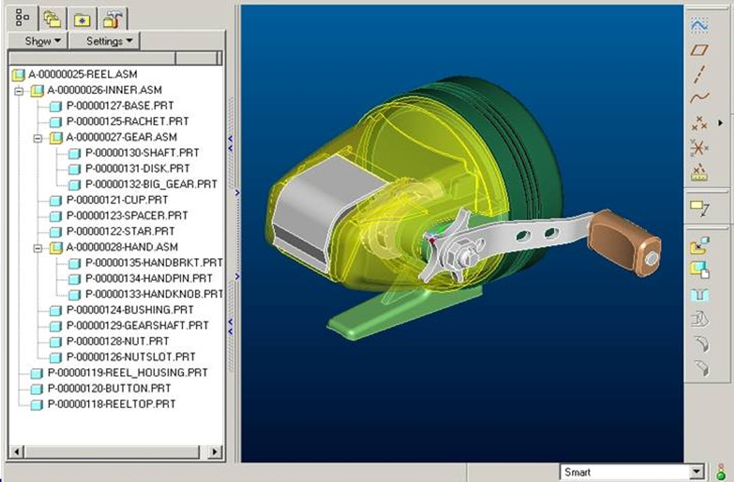 When building a product in a 3D CAD system, the concept is that you have individual parts designed in 3D. Every single part has a unique identifier.
If possible, the (file) name would equal the physical part number.
Next, a group of parts could be stored as a subassembly. Such an assembly is sometimes called a phantom assembly, in case they only group together several 3D parts. The usage of this type of assemblies increased CAD productivity. For data management reasons, these assemblies need to have a unique identifier, preferably not with the same numbering scheme for physical part numbers. It would consume part numbers that would never be used during manufacturing.
Note: in the early days of connecting 3D CAD to ERP, there was a considerable debate about which system could generate the part number.
ERP has always been the leading system for parts definition, why change ? And why generate part numbers that might not be used later in production. “Wasting” part numbers was a bad practice as historically, the part number was like a catalog number: 6 to 7 digits.
 Next, there is also another group of subassemblies that represent one or more primary components of a product. For example, a pump assembly, that might be the combination of the pump, the motor, and the base frame. This type of assembly appears most of the time high in the CAD-structure. They can be considered as a phantom assembly too, regarding a required identifier for this subassembly.
 Finally, there might be parts in the CAD-structure that will not exist in reality as part but need to be created during the manufacturing process. Sheet metal parts are created during the manufacturing process. Cappings, strips and cables shown in the CAD-structure might come from materials that are purchased in standardized sizes (1 meter / 2 meter / 10 meter) and need to be cut during manufacturing. Here the instances in the CAD-structure will have a unique identifier. What type of identifier to use depends on the manufacturing process. It might be a physical part number, as it is a half-fabricate, or it remains a unique identifier for the CAD-structure only.
The reason I am coming back to these identifiers is that as described before, companies wanted to keep a relation between the part number and the file name.
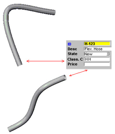 There was a problem with flexible parts. A rubber hose with a specific length could be shaped differently in an assembly based on its connection. Two different shapes would create two files and therefore break the rule of a part number equals file name. The 3D CAD vendors “solved” this issue by storing configurable views of the same part inside one file and allow the user to select the active view.
Later we will see that management of views inside the 3D CAD model is not a wrong choice. This, contrary to managing different configurations of a part/product inside a single file, which creates complexity in the PLM domain.
In the end, the product became an assembly with several levels of subassemblies. At that time, when I worked a lot with CAD-integrations, the average depth of 3D CAD-structures was 6 to 7 levels deep, with exceptions in both directions.
The entire product CAD-structure is mainly used for a final digital mock-up, to allow engineers to analyze the full product behavior. One of my favorite YouTube movies is the one from Airbus – seven years ago, they described the power of a full digital mock-up used for the A380.
In ETO-processes, the 3D CAD-structure is unique for a given customer solution – like the A380.
 In the case of large assemblies with a lot of parts and subassemblies, there were situations where the full product could not be resolved anymore. For Airbus a must, for the mid-market not always easy to reach. Graphics memory, combined with the way graphics were represented, are the major constraint. This performance issue is resolved in the gaming world, however then the 3D representation had no longer the required accuracy or definition.
The Version pop-up problem
 Working with a 3D CAD structure created a new problem when designers were sharing parts and assemblies between themselves and suppliers. The central storage of the files required a versioning mechanism, supported by a check-in and check-out mechanism.
Depending on the type of 3D CAD integration, the PDM system generated a new minor revision of the file after check-in again. In this way, there was full traceability of the changes before release. The image below shows an example of how SmarTeam was dealing with minor and major revisions combined with lifecycle stages.
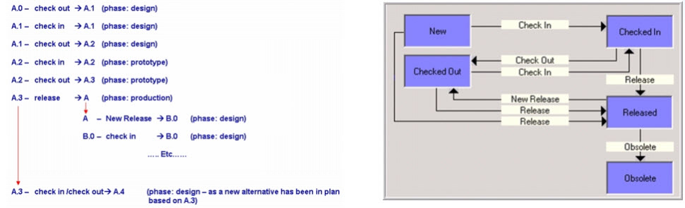
When revising a part, all assemblies that contained the changed part need to be updated too, in case you want to have traceability and preventing others from overwriting your version. Making sure this assembly file points to the right file again. In the cases of a 6-level deep CAD-structure, this has led to a lot of methodology problems on how to deal (or not to deal) with file changes.
In the case of a unique delivery for a customer, the ETO-process, the issue might not be so big. As everything in the 3D CAD-structure is work in progress, you only need to be sure during the release process of the 3D CAD-structure that all parts and assemblies are resolved to the latest version (and verified)
Making changes on an existing product is way more complicated, as assemblies are released, and parts exist in production. In that case, the Bill of Material is the leading structure to control the versions and the change impact, as we will see.
![]() Note: Most CAD- and PLM-vendors loved to show you their demos, where starting from the CAD-structure, a product gets created (the ETO-process). The reality is that most companies do not start from the CAD-structure, but from an existing Bill of Material. In 2010, I wrote a few posts, discussing the relation between CAD and the BOM:
Note: Most CAD- and PLM-vendors loved to show you their demos, where starting from the CAD-structure, a product gets created (the ETO-process). The reality is that most companies do not start from the CAD-structure, but from an existing Bill of Material. In 2010, I wrote a few posts, discussing the relation between CAD and the BOM:
to explain there is more than a CAD-driven scenario.
The EBOM
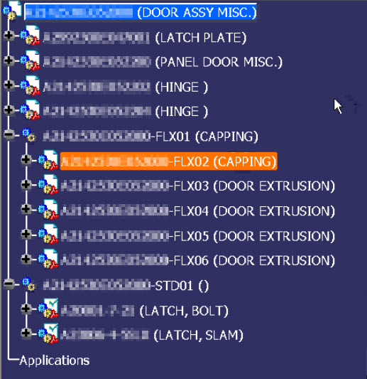
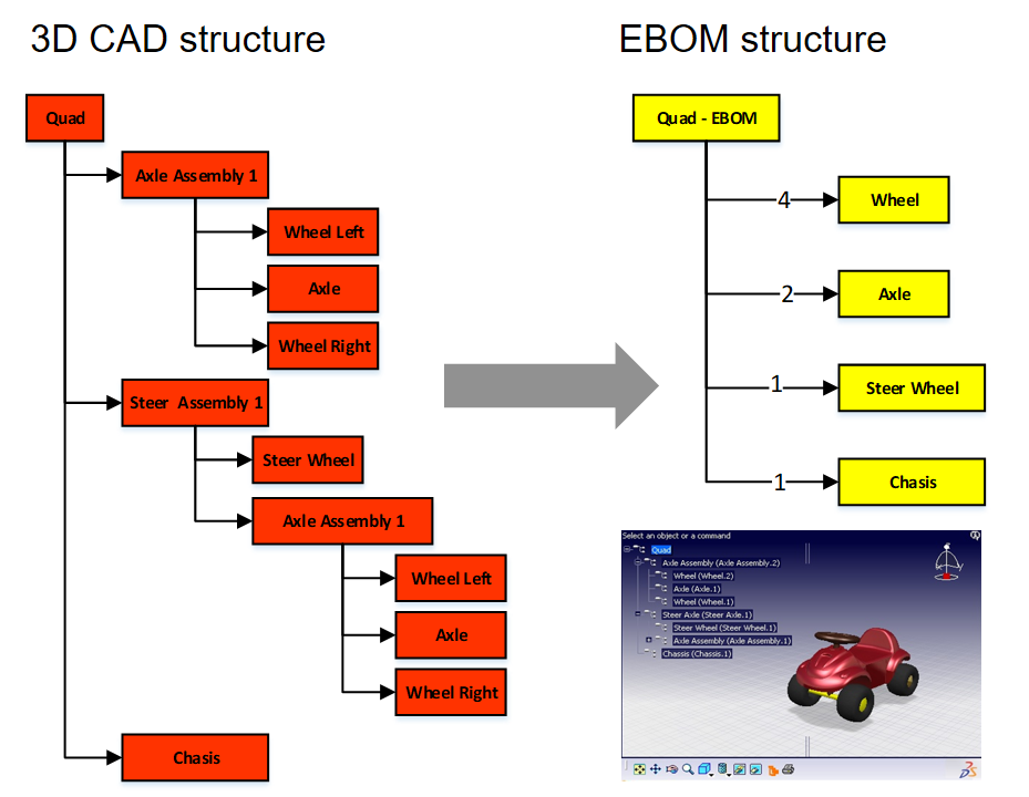
In most PDM-systems with CAD-integrations, it is possible to create a Bill of Materials from the 3D CAD-structure. The Bill of Materials will be based on the parts inside the 3D CAD-structure. There is often the option to filter out phantom assemblies.
The structures are not the same. The 3D CAD-structure is instance-based, where the extracted Bill of Materials will summarize the part quantities on the same level. See the image below. There are four Wheel instances in the CAD structure, in the EBOM-structure, we have only one Wheel reference with quantity 4.
I named the structure on the right the EBOM as the structure represents the Bill of Materials from the engineering point of view. This definition is a little arbitrary, as we will see. In companies that started to develop products based on a conceptual BOM, often, this conceptual BOM was an “early” EBOM that had to be developed further. This EBOM was more representing a logical or modular structure driving the design, instead of an extract from the 3D CAD-structure. In the next post, I will zoom in on these differences. I want to conclude this time with a critical methodology needed to manage the 3D CAD structure changes in relation to an EBOM.
Breaking the rule Drawing ID (Model ID) = Part ID
Although I have been writing mostly about the 3D CAD structure, I want to remind us that the 3D Model in the mid-market is mainly used for design purposes. The primary delivery for manufacturing or a supplier is still a 2D-drawing for most companies. The 3D Model might be “nice to have” for CAM- or quality usage. Still, in case of a dispute, the 2D Drawing will be leading.
For that reason, in many mid-market companies, there was the following relation below:
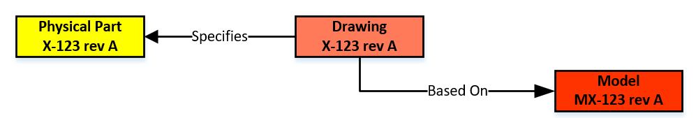
In an environment without file versioning through check-in/check-out, this relation was easy to maintain. In the electronic world, every change in the 3D Model (which could be an assembly) triggers a new file version and, therefore, most of the time, a new version of the drawing and the physical part. However, you do not want to have a physical part with many revisions, in particular when this part could be again part of a Bill of Material.
 To solve this issue, the Physical Part and the related Drawing/Model should have different lifecycles. The relation between the Physical Part and the Drawing Model should no longer be based on numbers but on a relation in the PDM/PLM-system. One of the main characteristics of a PDM/PLM-system is that it allows users to navigate through relations to find information in context. For example, solving a Where Used – question is a (few) mouse-click(s) in a PDM/PLM-system.
Click on the image to see the details.
Breaking this one-to-one numbering rule is a must if you want to evolve to an item-centric or data-driven PLM-environment. When to introduce this change and how to implement this new behavior is a methodology exercise, not an implementation of a new tool.
 There is a lot to read about this topic as it is related to the Form-Fit-Function-discussion we had earlier this year. A collection of information can be found in these two LinkedIn-post, where the comments are providing the insights:
- What the FFF is happening
- How to step beyond the complexity of Bill of Materials, Revisions and Change Management
I will not dive deeper into this theme (reached 1700 words ☹) – next time I will zoom in on the EBOM and leave the world of 3D CAD behind (for a while)
Discover more from Jos Voskuil's Weblog
Subscribe to get the latest posts sent to your email.

2 comments
Comments feed for this article
July 8, 2020 at 2:56 am
Lee Perrin
“…assemblies need to have a unique identifier, preferably not with the same numbering scheme for physical part numbers. It would consume part numbers that would never be used during manufacturing.”
I would contend that using the same numbering scheme would allow for consistency across the drawing numbering system, and in manufacturing. Further, since the assemblies need to have a number, why not depict them on a drawing, and show the EBOM either on the face of that drawing, or as an attached part list? Then Mfg Eng can receive these drawings and incorporate them into shop travelers and work instruction, and MBOMS as needed. Here you would have the collection of the needed parts to bring together into the assembly.
In this discussion, you do touch on, ever so slightly, intelligent vs. non-intelligent numbering systems. I look forward to your thoughts on these to follow.
Hi Lee, the reason I am referring to a different numbering scheme for subassemblies is the fact that in real life, they will not exist. They are a logic grouping done by engineers, and these assemblies, as such, will not appear on a drawing. The parts in a subassembly will appear on a drawing, mostly the level above.
Using 3D CAD as a tool creates the need to make this kind of decisions; otherwise, you create either noise (part numbers that do not exist / part numbers that create extra work) or inconsistent ways of working (keeping 3D Assembly = Part = Drawing )
Related to BOM handling, I am currently writing the EBOM part. There is a lot to explain there too, as although we believe the EBOM-definition is clear, in reality, it is not – it can be a hybrid EBOM/MBOM (historical mostly done) or a pure EBOM (modular for engineering collaboration) or something derived from CAD.
So please stay with me the upcoming weeks for the full answer—Best Regards, Jos.
LikeLike
July 15, 2020 at 2:04 pm
Riaan Havenga
Thanks Jos, a good introductory article to the complexities of BOM management. This all so familiar. 😉
The one aspect which also needs careful consideration is in managing the production and manufacturing related data, which will have a different lifecycle than the as-designed part. Things like the condition of supply 3D models – for example, the model for a casting, etc – a new number?
Keep up the good work, I hope you continue this thread up to the As-manufactured and in Service BOM’s
Kind Regards
Riaan
Thanks Riaan, great hearing from you and it should be familiar to you 🙂 The points you are addressing are also important, at this moment not in my plan. I plan to follow the path from 2D Drawings – towards 3D CAD structure – leading to BOM – from here understanding the split between manufacturing and engineering BOM – seeing the value of the service BOM and ultimate discovering these BOM-structures are not the future for a model-based enterprise. Many parts to come. Somewhere (soon) I might need to address already the move from 2D Drawings as the master to MBD. It feels like writing a book – step by step.
Always feel free to chime in and share your practices like Jean-Jacques Urban-Galindo contributed with the PSA case. Best regards Jos.
LikeLike