
 To understand our legacy in the PLM-domain, what are the types of practices we created, I started this series of posts: Learning from the past to understand the future. My first post (The evolution of the BOM) focused on the disconnected world between engineering – generation of drawings as a deliverable – and execution MRP/ERP – the first serious IT-systems in a company.
At that time, due to minimal connectivity, small and medium-sized companies had, most of the time, an informal connection between engineering and manufacturing. I remember a statement at that time, PLM was just introduced. One person during a conference claimed:
“You guys make our lives so difficult with your systems. If we have a problem, we gather around the machine, and we fix it.”
PLM started at large enterprises
Of course, large enterprises could not afford such behavior as they operate globally. The leading enterprises for PDM/PLM were the Aerospace & Defense and Automotive companies. They needed consistent processes and formal ways of working to guarantee quality output.
 In that sense, I was happy with the reaction from Jean-Jacques Urban-Galindo, who shared in the LinkedIn comments a reference to a relevant chapter of John Stark’s PLM book. In the pdf describing the evolution of CAD / PDM / PLM at PSA. Jean-Jacques was responsible at that time for Responsible for the re-engineering of the Product & Process Engineering processes using digital tools (CAD/CAM, DMU, and more).
Read the PSA story here: PLM at GROUPE PSA. It describes nicely where 3D CAD and EBOM are coming in. In large enterprise like PSA, the need for tools are driven by the processes. When you read it to the end, you will also see the need for a design and a manufacturing view. A topic I will touch in future posts too.
The introduction of 3D CAD in the mid-market
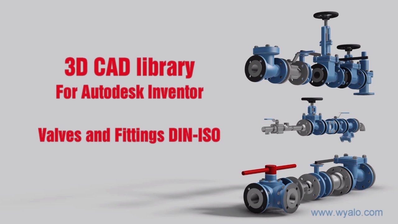
 Where large automotive and aerospace companies already invested in (expensive) 3D CAD hard and software, for the majority of the midsize companies, the switch from 2D CAD (AutoCAD mainly) towards 3D CAD (SolidWorks, Solid Edge, Inventor) started at the end of the 20th century.
It was the time that Microsoft NT became a serious platform beside the existing mainframe and mini-computer based CAD-systems. The switch to PCs went so fast that the disruption from DEC (Digital Equipment Company) is one of the cases discussed by Clayton Christensen in his groundbreaking book: The Innovator’s dilemma
 3D CAD introduced a lot of new capabilities, like DMU (Digital Mock-Up), for clash detection, and above all, a better understanding of a product’s behavior. The introduction of 3D CAD introduced a new set of challenges to be resolved.
For example, the concept of reusing 3D CAD parts. Mid-market companies, most of the time, are buying productivity tools. Can I design my product faster and with higher quality in 3D instead of using only the 2D definitions?
Mid-market companies usually do not redesign their business processes – no people available for strategy – the pain of lack of strategy is felt in a different way compared to large enterprises—a crucial differentiator for the future of PLM.
Reuse of (3D) CAD parts / Assemblies
 In the 2D CAD world, there was not so much reuse of CAD parts. Standard parts were saved in libraries or generated on demand by parametric libraries. Now with 3D CAD, designers might spend more time to define the part. The benefits come from the reuse of small sub-assemblies (modules) into a larger product assembly. Something not relevant in the 2D CAD world.
 As every 3D CAD part had to have a file name, it became difficult to manage the file names without a system. How do you secure that the file with name Part01.xxx is unique? Another designer might also create an assembly, where the 3D CAD tool would suggest Part01.xxx as the name. And what about revisions? Do you store them in the filename, and how do you know you have the correct and latest version of the file?
Companies had already part naming rules for drawings, often related to the part’s usage similar to “intelligent” numbers I mentioned in my previous post.
With 3D CAD it became a little more complicated as now in electronic formats, companies wanted to maintain the relation:
Drawing ID = Part ID = File Name
The need for a PDM-system,
 If you look to the image on the left, which I found in one of my old SmarTeam files, there is a part number combined with additional flags A-A-C, which also have meaning (I don’t know ☹ ) and a description.
The purpose of these meaningful flags was to maintain the current ways of working. Without a PDM-system, parts of the assembly could be shared with an OEM or a supplier. File-based 3D CAD without using a PDM-system was not a problem for small and medium enterprises.
The 3D CAD-system maintained the relations in the assembly files, including relations to the 2D Drawings. Despite the introduction of 3D CAD, the 2D Drawing remained the deliverable the rest of the company or supply chain, was waiting for. Preferably a drawing containing a parts list and balloon numbers, the same as it has been done before. Why would you need a PDM-system?
PDM for traceability and reuse
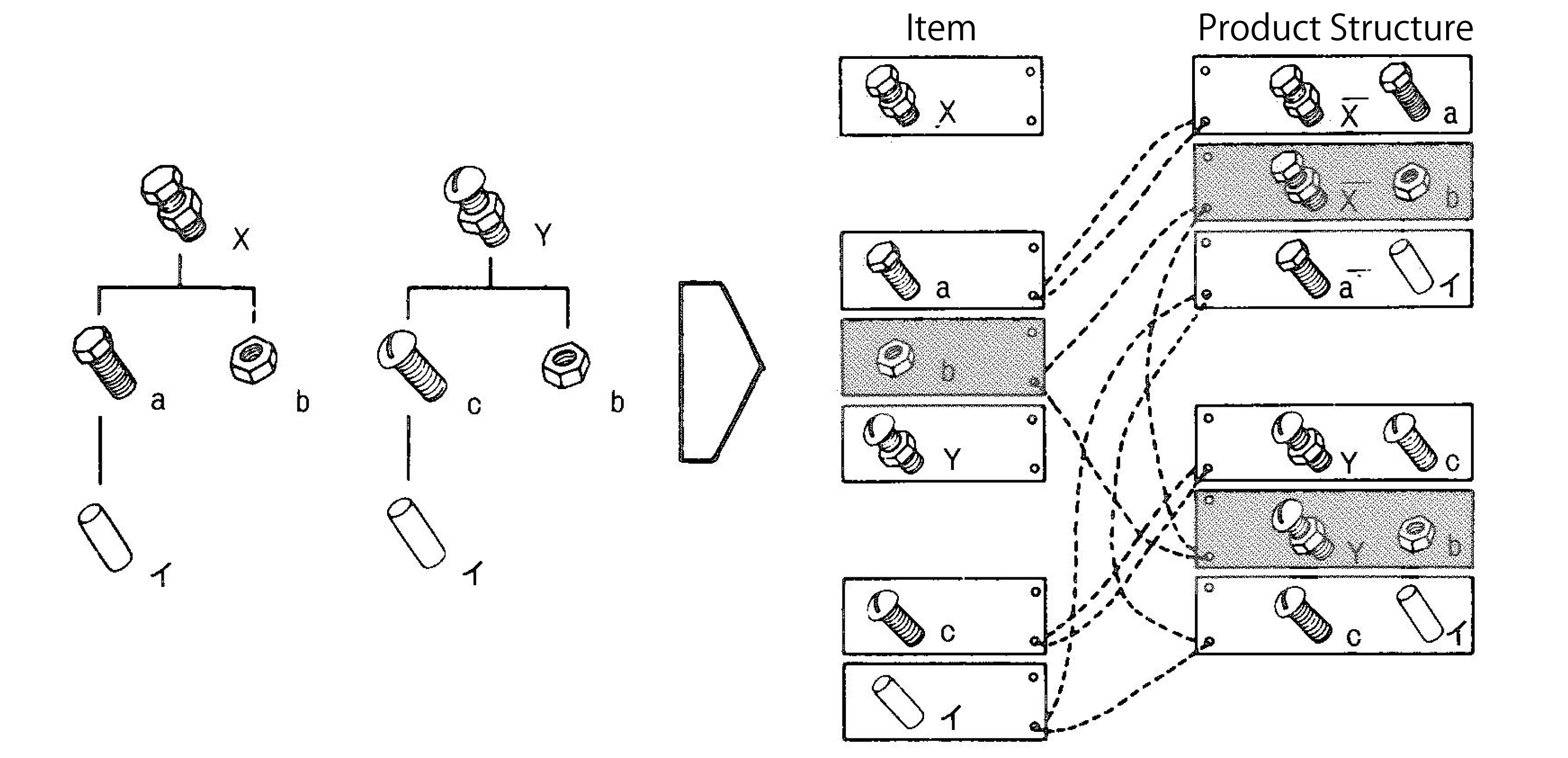
 If you were working in your 3D CAD-system for a single product, or on individual projects for OEMs, there was no significant benefit for a PDM-system. All deliveries needed for the engineering department were in the 3D CAD environment. Assembly files and drawing files are already like small databases, containing references to the source files of the part (image above).
A PDM-system at this stage could help you build traceability and prevent people from overwriting files. The ROI for this part only depends on the cost and risks of making mistakes.
However, when companies started to reuse parts or subassemblies, there was a need for a system that could manage the 3D models separately. This had an impact on the design methodology.
 Now parts could be used in various products. How do you discover parts for reuse, and how do you know you have the last released version. For sure their naming cannot be related anymore to a single product or project (a practice still used a lot)
This is where PDM-systems came in. Using additional attributes per file combined with relations between parts, allowing companies to structure and deliver more details related to a part. A detailed description for internal usage, a part type (classification), and the part material were commonly used attributes. And not to forget the status and revision.
 For reuse, it was important that the creators of content had a strategy to define a part for future reuse or discovery. Engineerings were not used to provide such services, filling in data in a PDM-system was seen as an overhead – bureaucracy.
As they were measured on the number of drawings they produced, why do extra work with no immediate benefits?
The best compromise was to have the designer fill in properties in the CAD-file when creating a part. Using the CAD-integration with the PDM-system could be used to fill attributes in the PDM-system.
This “beautiful” simple concept lead later to a lot of complexity.
Is the CAD-model the source of data, meaning designers should always start from CAD when designing a product. If someone added or modified data in the PDM-system, should we open the CAD-file to update some properties? Changing a file means it is a new version. What happens if the CAD-file is released, and I update some connected attributes in PDM?
 To summarize this topic. Companies have missed the opportunity here to implement data governance. However, none of the silos (manufacturing preparation, service) recognized the need. Implementing new tools (3D CAD and PDM) did not affect the company’s way of working.
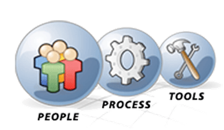
Instead of people, processes, tools, the only focus was on new tools and satisfying the people withing the same process.
 Of course, when introducing PDM, which happened for mid-market companies at the beginning of this century, there was no PLM vision. Talking about lifecycle support was a waste of time for management. As we will discover in the future posts, large enterprises and small and medium enterprises have the same PLM needs. However, there is already a fundamentally different starting point. Where large enterprises are analyzing and designing business processes, the small and medium enterprises are buying tools to improve the current ways of working
The Future?
 Although we have many steps to take in the upcoming posts, I want to raise your attention to an initiative from the PLM Interest Group together with Xlifecycle.com. The discussion is about what will be PLM’s role in digital transformation.
As you might have noticed, there are people saying the word PLM is no longer covering the right context, and all kinds of alternatives have been suggested. I recommend giving your opinion without my personal guidance. Feel free to answer the questionnaire, and we will be all looking forward to the results.
Find the survey here: Towards a digital future: the evolving role of PLM in the future digital world
Conclusion
We are going slow. Discovering here in this post the split in strategy between large enterprises (process focus) and small and medium enterprises (tool focus) when introducing 3D CAD. This different focus, at this time for PDM, is one of the reasons why vendors are creating functions and features that require methodology solving – however, who will provide the methodology.
Next time more on 3D CAD structures and EBOM
Discover more from Jos Voskuil's Weblog
Subscribe to get the latest posts sent to your email.

Leave a comment
Comments feed for this article