
You are currently browsing the tag archive for the ‘Configure To Order’ tag.
In this post in the series Learning from the past to understand the future, I want to leave the 3D CAD structures behind. But before doing so, I want to mention some of the lessons learned:
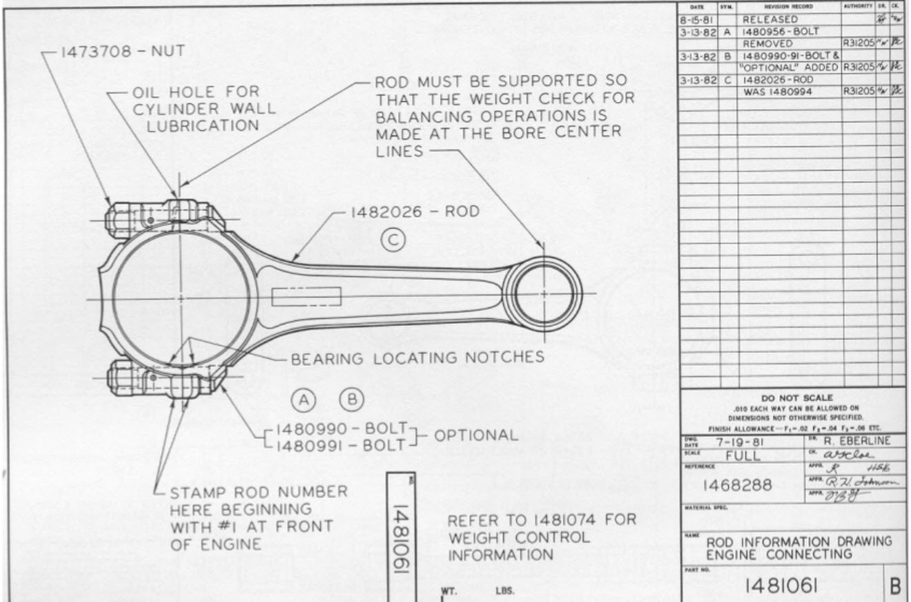
![]() In Part 1: “Intelligent” drawing numbers were the source for “intelligent” part numbers as often there was a one-to-one relationship between the drawing and the part(s) on a drawing.
In Part 1: “Intelligent” drawing numbers were the source for “intelligent” part numbers as often there was a one-to-one relationship between the drawing and the part(s) on a drawing.
 In Part 2: 3D CAD has been introduced in the automotive and aerospace industry due to process optimization, where a 3D CAD environment created better collaboration possibilities (DMU). The introduction of 3D CAD in the mid-market was different. Here 3D CAD is used as an engineering tool, not changing any processes.
The complexity grew because also file names needed to be managed, introducing the need for PDM-systems.
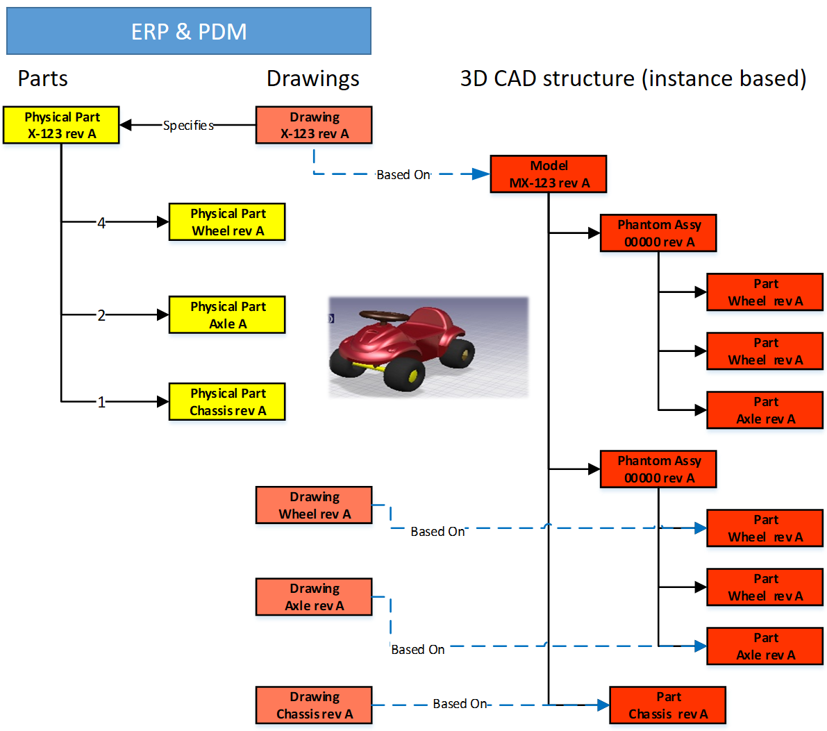
![]() In Part 3: we discussed the challenges of working with file-based 3D CAD structures. The versioning problem with check-in/check-out of structure in particular in the case of data reuse. Here the best practice was introduced to have physical parts with a different lifecycle than 3D CAD parts and assemblies.
In Part 3: we discussed the challenges of working with file-based 3D CAD structures. The versioning problem with check-in/check-out of structure in particular in the case of data reuse. Here the best practice was introduced to have physical parts with a different lifecycle than 3D CAD parts and assemblies.
Now engineers need to create valid configurations based on links between the physical part and the 3D/2D object. This requires a PDM-system with BOM and CAD-files as standard information objects.
 In Part 4: we discussed the relations between the BOM and 3D CAD structures without neglecting the fact the 2D Drawing is still the primary legal information carrier for manufacturing/suppliers. The point discussed in this post was the fact that most companies used a kind of ETO-approach. Starting from the 3D CAD-system, adding sometimes manufacturing parts in this structure, to generate a BOM that can be served as input for the ERP-system.
I want to follow up from the last conclusion:
Changing from ETO to CTO requires modularity and a BOM-driven approach. Starting from a 3D CAD-structure can still be done for the lowest levels – the modules, the options. In a configure to order process, it might not be relevant anymore to create a full 3D-representation of the product.
Starting from a conceptual structure
 Most companies that deliver products to the market do not start from scratch, as we discussed. They will start from either copying an existing product definition (not recommend) or trying to manage the differences between them, meanwhile keeping shared components under revision control.
 This cannot be done based on 3D CAD-structures anymore. At that time (we are in the early 2000s) in the mid-market, the PDM-system was used to manage these structures, in particular, they used the BOM-capabilities.
The BOM-structure was often called the EBOM, as engineers were defining the EBOM. But is it really an EBOM? Let us have a look wat defines an EBOM.
What characterizes an EBOM?
There are many personal definitions of what is considered as an EBOM. Also, the Wiki-definition here does not help us a lot. So here is my personal 2004 definition:
- The EBOM reflects the engineering view of a product and, therefore, can have a logical structure of assemblies and subassemblies based on functionality, modularity, and standardization.
- The EBOM is a part structure specifying a product from its design intent, specifying parts, materials, tolerances, finishing.
- The EBOM-structure is allowing multidisciplinary teams to work together on a joint definition of the product
The picture below illustrates the above definition.
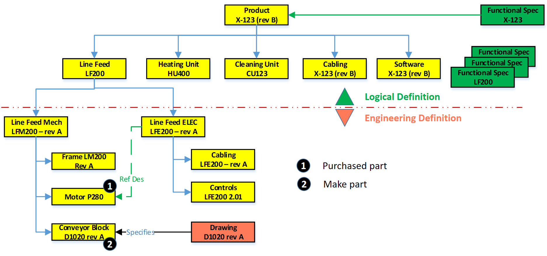
In this EBOM-structure, we see that the first two levels actually are more a logical division of functional groups, either as units, product/discipline-specific definitions (cabling/software). These components should not be in the EBOM if you have support for logical structures in your PLM-environment. However, in 2004 – PLM was not that mature in the mid-market, and this approach was often chosen.
If we look at the Line Feed module, which could also be used in other products, there is the typical mechanical definition and in parallel the electrical definition. Having them inside a single EBOM gives the advantage of being able to do a “where-used” and status/impact-analysis.
1 – Purchased parts
 Motor P280 is an interesting EBOM-part to consider. This motor is required; however, in an EBOM, you should not specify the supplier part number directly. As supplier part availability and preference will change over time, you do not want to revise the EBOM every time a supplier part gets changed.
 Therefore, the Motor P280 should have an internal part number in the EBOM. Next, it will be engineering that specifies which motors fulfill the need for Motor P280. Preferably they will create an Approved Manufacturing List for this motor to give manufacturing/purchasing the flexibility to decide per order where to purchase the motor and from which supplier.
The relation between the Approved Manufacturing List and the Approved Vendor List is shown in the diagram above.
![]() Or follow the link to this image to read more in Arena’s glossary. In particular, for electronic components, this concept is needed as high-level specifications for electronic parts might be the same.
Or follow the link to this image to read more in Arena’s glossary. In particular, for electronic components, this concept is needed as high-level specifications for electronic parts might be the same.
However, the details (tolerances/environment) can be decisive, which component is allowed. Besides, due to the relatively short lifecycle of electronic components, the EBOM needs to be designed in such a manner to anticipate changes in suppliers.
 You can only benefit from this approach if, from the beginning of your designs, there are no supplier-specific parts in your EBOM. For Engineering, to Order companies that want to become more Build to Order, this is a challenging but critical point to consider.
Note: The functional characteristics for the motor will come from the electrical definition, and through a reference designator, we create the link between the functional definition and the physical implementation in the product.
2 – Make Parts
 Secondly, if we look to the conveyor block D1020 rev A, this block is a make part, with probable a whole assembly of parts below it. As it is a make part, there is at least an assembly drawing and, more likely, a related technical data package linked to D1020 rev A. Make parts still carry a revision as here the Form-Fit-Function discussion can be used when implementing a change of the part.
Note: I used for the final assembly drawing the same number scheme as this is how most companies work. However, in my previous post, I described that if you have a PDM-system in place, the numbering can be different. Maintaining the relations between a part and the related drawing is, in this case, crucial.
The Configured EBOM
 The image on the left, we used to illustrate the typical mid-market EBOM in a PDM-system, will become more complicated if we also add options and variants to the EBOM. I assume you know the difference between a variant and an option.
In this case, the EBOM the definition for the full product range. Actually, the top part of the EBOM does not exist as an instance. It is the placeholder to select a resolved EBOM for a specific product configuration. For the ease of use, I have simplified the initial diagram, now zooming in on variants and options, apologizing for my artistic capabilities as the purpose of a blog is different from a book.
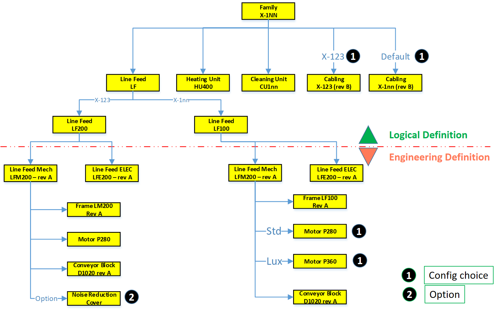
If we look at the diagram, this configured structure contains variants and options.
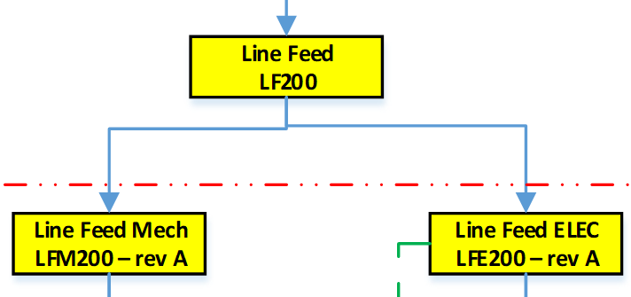 First, on the logical definition, we see a new grouping. There are two types of Line Feed available, one specific for the X-123 and a later, more generic designed LF100, suitable for all X-1nn variants.
As the LF100 is more generic designed, the customer can select between two motors, the standard P280 and the more advanced version P360, with better service capabilities.
![]() For the Line Feed LF200, there is an option to order a Noise Reduction Cover. It was sold once to an existing customer, and as the cover fits all X-123, it has been linked here as an option to the X-123 definition. So, the customer solution with the Noise Reduction Cover does not have an isolated, copied structure in the EBOM.
For the Line Feed LF200, there is an option to order a Noise Reduction Cover. It was sold once to an existing customer, and as the cover fits all X-123, it has been linked here as an option to the X-123 definition. So, the customer solution with the Noise Reduction Cover does not have an isolated, copied structure in the EBOM.
Also, in the Logical Structure, we see there is a cabling definition for the X-123 or the default cabling set for all other products.
 The diagram illustrates what many mid-market companies have been doing more or less in their PDM-system to avoid copying of EBOM structures per customer order.
It is an example of where a tool (the PDM-system) is slowly abused for administrative reasons. Let me explain why.
The link between Products and (E)BOMs
If we look at the upper part of the configured EBOM structure, this is a logical product definition. Or to say it in different words, it is a portfolio definition, which products and modules a company can sell to the market. Some of the grouping of the portfolio is purely based on business reasons, which products and options do we want to sell.

In most companies, the product portfolio is managed in (marketing) documents without a direct connection to the engineering world. However, we will see in an upcoming post, this relation is crucial for a digital enterprise. Meanwhile, look at on old blog post: Products, BOMs and Parts if you want to be faster
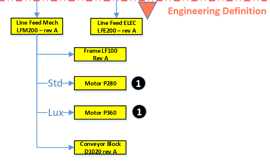 The Engineering definition below the red dashed line is a real EBOM, representing the engineering definition of a system, a module, or a component. When these systems and modules are defined in a single structure that can be filtered based on selection criteria, we talk about a Configured EBOM or sometimes a 150 % EBOM.
Each of the components in the configured EBOM can have a related 3D CAD structure or specification that can be developed traditionally.
The result of a resolved EBOM is a variant that can be delivered to the customer. In this EBOM-driven approach, there is not always a full 3D-representation of the customer product.
![]() Again, size (1500+) words make me stop this story, where next time we will go from product to EBOM and introduce the need for an MBOM in specific industries.
Again, size (1500+) words make me stop this story, where next time we will go from product to EBOM and introduce the need for an MBOM in specific industries.
Conclusion
A pure EBOM only specifies a product and contains all relevant information in context – designs & specifications. The EBOM should not be mixed or confused with a logical grouping, belonging to a portfolio definition (even if the system allows you to do it)
On my previous post shared on LinkedIn Ilan Madjar, a long-time PLM colleague reacted with the following point (full thread here)

Ilan is pointing to the right challenge in many companies. Changing the way you work is though exercise and requires a good understanding, vision, and execution to move forward. Do not trust the tool to work for you – it is about human understanding and process re-engineering to be more efficient. And if you do not practice this on the basic PDM-level as discussed so far, imagine the impossibility of going through a digital transformation.
 This is the third post on Bill of Material handling for different types of companies, this time the focus on Configure To Order (CTO). In the CTO process, products are assembled and configured based on customer requirements. This means there is no more engineering needed when customer requirements are known. CTO examples are, the ordering process of a car with all its options, or ordering a personal computer over the internet.
So what has Configure To Order to do with PLM as there is no engineering?
The main PLM activity takes places when designing the configurable product. Designing a product that is configurable, requires a complete different approach as compared to Engineering to Order or Build to Order. Although we see a similar Configure to Order activity in the R&D departments of companies that follow the Build to Order process. They are also designing products or modules that can be used as-is in customer specific orders as part of the solution.
 The challenge of CTO is to design products that are modular, and where options and variants are designed on a common platform with common interfaces. If you look to the dashboard of a car you will see placeholders for additional options (in case you have the minimal car version) and also you might see that for example the radio display in a basic car version differs from the complete board computer in the luxury version. The common platform is one dashboard, fitting to numerous options.
An engineering department will not focus on designing and defining each of the possible combinations of options as this would be impossible to manage. What can be managed is the common platform (the baseline) and all different options on top of this baseline.
So what happens with the BOM?
The initial design of configurable products goes through similar steps as the BTO process, which means starting from a conceptual BOM, moving to an Engineering BOM (eBOM) and finally produce a BOM for manufacturing (mBOM). The difference is that in the CTO process the mBOM is not developed for just one product, but contains all definitions for all possible products. In this situation we talk about a generic mBOM.
Only when a customer order exists, the generic mBOM is resolved into a specific mBOM for this customer order, which then can be sent to the ERP system for execution.
 In a generic BOM the relations are managed by filters. These filters define the effectivity of the link, in simple words if the relation between two parts in the BOM is valid (and shown) or not. There are various ways to define effectivity – with again a differentiation in usage
- revision based effectivity – which means the relation between two items is valid in case the revisions match
- date effectivity – which means the relation is valid during a certain time interval
Both methods are used most of the time for non-configurable products. The revision and date effectivity are used to be able to track the product history through time and therefore to have full traceability. But this does not work if you want to configure every time a customer specific order.
In that case we use unit or option based filtering.
- unit effectivity – which means the relation between two items is valid for a unit (or a range of units) produced. For example a batch of products or a unique product with a serial number
- option effectivity – which means the relation between two items is valid in case a certain condition is valid. Which condition depends on the configuration rules for this option. Example of options are: color, version, country
It is clear that unit and option based filtering of a BOM can lead to a conceptual complex product definition which goes beyond the BOM for Dummies target. Below an illustration of the various filter concepts (oops the animated gif does not work – i will investigate):

The benefit of this filtering approach is that there is a minimum of redundancy of data to manage. This makes it a common practice in the aerospace and automotive industry. An example describing all the complexity can be found for example here, but I am sure on this level there are enough publications and studies available.
And what about the CAD ?
I will write a separate post on this topic, as all the possible interactions and use cases with CAD are a topic on its own. You can imagine, having the 3D virtual world combined with a configurable BOM brings a lot of benefits
What PLM functions are required to support Configure to Order ?
- Project management – not so much focus here as the delivery project for a customer does not require much customer interaction. Of course, the product development processes requires advanced capabilities which I will address later in a future post.
- Document management – same approach as for project management. The product related documentation needs to exist and secured. Customer specific documentation can be generated often automatically.
- Product Management – managing all released and available components for a solution, related to their Bill of Materials. Often part of product management is the classification of product families and its related modules
- Item management – The main activities here are in the mBOM area. Capabilities for BOM generation (eBOM/mBOM), baseline and compare using filtering (unit based / option based) in order to support the definition if the manufactured product
- Workflow processes – As we are dealing with standardized components in the BOM, the Engineering Change Request (ECR) and Engineering Change Order (ECO) processes will be the core for changes. And as we want to manage controlled manufacturing definition, the Manufacturer Change Order process and Standard Item Approval process are often implemented
Optional:
- Requirements Management – specially for complex products, tracking of individual requirements and their implementation, can save time and costs during delivery to understand and handle the complex platform
- Service Management – as an extension of item management. When a customer specific order has been delivered it might be still interesting for the company that delivered the product to keep traceability of the customer configuration for service options – managing the Service and As-Built BOM
- Product Configurator – the reason I write it as optional, is because the target is order execution, which is not a PLM role anymore. The ERP system should be able to resolve the full mBOM for an order. The PLM product configuration definition is done through Product and Item management. Depending on the customer environment the role of configurator might be found in PLM in case ERP does not have the adequate tools.
Conclusion:
It is hard to describe the Configure To Order process in the scope of BOM for Dummies. As various detailed concepts exist per industry there is no generic standard. This is often the area where the PLM system, the PLM users and implementers are challenged the most: to make it workable, understandable and maintainable
Next time some industry specific observations for a change

Hi Jos, Knowing your background in methodology and education, I wanted to share a longer article with you: “What is…
Interesting reflection, Jos. In my experience, the situation you describe is very recognizable. At the company where I work, sustainability…
[…] (The following post from PLM Green Global Alliance cofounder Jos Voskuil first appeared in his European PLM-focused blog HERE.) […]
[…] recent discussions in the PLM ecosystem, including PSC Transition Technologies (EcoPLM), CIMPA PLM services (LCA), and the Design for…
Jos, all interesting and relevant. There are additional elements to be mentioned and Ontologies seem to be one of the…