
You are currently browsing the category archive for the ‘PLM’ category.
In the last two weeks, three events were leading to this post.
 First, I read John Stark’s recent book Products2019. A must-read for anyone who wants to understand the full reach of product lifecycle related activities. See my recent post: Products2019, a must-read if you are new to PLM
Afterwards, I talked with John, discussing the lack of knowledge and teaching of PLM, not to be confused by PLM capabilities and features.
 Second, I participated in an exciting PI DX USA 2020 event. Some of the sessions and most of the roundtables provided insights to me and, hopefully, many other participants. You can get an impression in the post: The Weekend after PI DX 2020 USA.
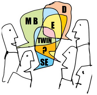
A small disappointment in that event was the closing session with six vendors, as I wrote. I know it is evident when you put a group of vendors in the arena, it will be about scoring points instead of finding alignment. Still, having criticism does not mean blaming, and I am always open to having a dialogue. For that reason, I am grateful for their sponsorship and contribution.
Oleg Shilovitsky mentioned cleverly that this statement is a contradiction.
![]()
“How can you accuse PLM vendors of having a limited view on PLM and thanking them for their contribution?”
I hope the above explanation says it all, combined with the fact that I grew up in a Dutch culture of not hiding friction, meanwhile being respectful to others.
We cannot simplify PLM by just a better tool or technology or by 3D for everybody. There are so many more people and processes related to product lifecycle management involved in this domain if you want a real conference, however many of them will not sponsor events.
 It is well illustrated in John Stark’s book. Many disciplines are involved in the product lifecycle. Therefore, if you only focus on what you can do with your tool, it will lead to an incomplete understanding.
If your tool is a hammer, you hope to see nails everywhere around you to demonstrate your value
 The thirds event was a LinkedIn post from John Stark – 16 groups needing Product Lifecycle Knowledge, which for me was a logical follow-up on the previous two events. I promised John to go through these 16 groups and provide my thoughts.
Please read his post first as I will not rewrite what has been said by John already.
CEOs and CTOs
 John suggested that they should read his book, which might take more than eight hours. CEOs and CTOs, most of the time, do not read this type of book with so many details, so probably mission impossible.
They want to keep up with the significant trends and need to think about future business (model).
New digital and technical capabilities allow companies to move from a linear, coordinated business towards a resilient, connected business. This requires exploring future business models and working methods by experimenting in real-life, not Proof of Concept. Creating a learning culture and allowing experiments to fail is crucial, as you only learn by failing.
CDO, CIOs and Digital Transformation Executives
 They are the crucial people to help the business to imagine what digital technologies can do. They should educate the board and the business teams about the power of having reliable, real-time data available for everyone connected. Instead of standardizing on systems and optimizing the siloes, they should assist and lead in new infrastructure for connected services, end-to-end flows delivered on connected platforms.
These concepts won’t be realized soon. However, doing nothing is a big risk, as the traditional business will decline in a competitive environment. Time to act.
Departmental Managers
 These are the people that should worry about their job in the long term. Their current mission might be to optimize their department within its own Profit & Loss budget. The future is about optimizing the information flow for the whole value chain, including suppliers and customers.
I wrote about it in “The Middle Management Dilemma.” Departmental Managers should become more team leaders inspiring and supporting the team members instead of controlling the numbers.
Products Managers
 This is a crucial role for the future, assuming a product manager is not only responsible for the marketing or development side of the product but also gets responsibility for understanding what happens with the product during production and sales performance. Understanding the full lifecycle performance and cost should be their mission, supported by a digital infrastructure.
Product Developers
They should read the book Products2019 to be aware there is so much related to their work. From this understanding, a product developer should ask the question:
“What can I do better to serve my internal and external customers ?”
 This question will no arise in a hierarchical organization where people are controlled by managers that have a mission to optimize their silo. Product Developers should be trained and coached to operate in a broader context, which should be part of your company’s mission. Too many people complain about usability in their authoring and data management systems without having a holistic understanding of why you need change processes and configuration management.
Product Lifecycle Management (PLM) deployers
Here I have a little bit of the challenge that this might be read as PLM-system users. However, it should be clear that we mean here people using product data at any moment along the product lifecycle, not necessarily in a single system.
This is again related to your company’s management culture. In the ideal world, people work with a purpose and get informed on how their contribution fits the company’s strategy and execution.

Unfortunately, in most hierarchical organizations, the strategy and total overview get lost, and people become measured resources.
New Hires and others
John continues with five other groups within the organization. I will not comment on them, as the answers are similar to the ones above – it is about organization and culture.
Educators and Students
 This topic is very close to my heart, and one of the reasons I continue blogging about PLM practices. There is not enough attention to product development methodology or processes. Engineers can get many years of education in specific domains, like product design principles, available tools and technologies, performing physical and logical simulations.
Not so much time is spent on educating current best practices, business models for product lifecycle management.
 Check in your country how many vendor-independent methodology-oriented training you can find. Perhaps the only consistent organization I know is CIMdata, where the challenge is that they deliver training to companies after students have graduated. It would be great if education institutes would embed serious time for product lifecycle management topics in their curriculum. The challenge, of course, the time and budget needed to create materials and, coming next, prioritizing this topic on the overall agenda.
 I am happy to participate to a Specialized Master education program aiming at the Products and Buildings Digital Engineering Manager (INGENUM). This program organized by Arts Et Metiers in France helps create the overview for understanding PLM and BIM – in the French language as before COVID-19 this was an on-site training course in Paris.
Hopefully, there are more institutes offering PLM eductation – feel free to add them in the comments of this post.
Consultants, Integrators and Software Company Employees
 Of course, it would be nice if everyone in these groups understands the total flow and processes within an organization and how they relate to each other. Too often, I have seen experts in a specific domain, for example, a 3D CAD-system having no clue about revisioning, the relation of CAD to the BOM, or the fundamentals of configuration management.
Consultants, Integrators and Software Company Employees have their own challenges as their business model is often looking for specialized skills they can sell to their clients, where a broader and general knowledge will come from experience on-the-job.
And if you are three years working full-time on a single project or perhaps work in three projects, your broader knowledge does not grow fast. You might become the hammer that sees nails everywhere.
 For that reason, I recommend everyone in my ecosystem to invest your personal time to read related topics of interest. Read LinkedIn-posts from others and learn to differentiate between marketing messages and people willing to share experiences. Don’t waste your time on the marketing messages and react and participate in the other discussions. A “Like” is not enough. Ask questions or add your insights.
 In the context of my personal learning, I mentioned that I participated in the DigitalTwin-conference in the Netherlands this week. Unfortunately, due to the partial lockdown, mainly a virtual event.
I got several new insights that I will share with you soon. An event that illustrated Digital Twin as a buzzword might be hype, however several of the participants illustrated examples of where they applied or plan to apply Digital Twin concepts. A great touch with reality.
 Another upcoming conference that will start next week in the PLM Roadmap 2020 – PDT conference. The theme: Digital Thread—the PLM Professionals’ Path to Delivering Innovation, Efficiency, and Quality is not a marketing theme as you can learn from the agenda. Step by step we are learning here from each other.
Conclusion
John Stark started with the question of who should need Product Lifecycle Knowledge. In general, Knowledge is power, and it does not come for free. Either by consultancy, reading or training. Related to Product Lifecycle Management, everyone must understand the bigger picture. For executives as they will need to steer the company in the right direction. For everyone else to streamline the company and enjoy working in a profitable environment where you contribute and can even inspire others.
An organization is like a human body; you cannot have individual cells or organs that optimize themselves only – we have a name for that disease. Want to learn more? Read this poem: Who should be the boss?
![]() It was a pleasure to participate this last week in the PI DX USA conference for several reasons. First, because Marketkey has been able to organize the event in the same manner as before. Meaning presentations, networking meetings, and roundtable discussions. Virtual, of course, however, in the same spirit. Secondly, the 3-day event took place during a late afternoon for Europe lasted 4 – 5 hours per day, allowing a larger audience to learn from each other. Before we had the European viewpoints and American viewpoints separate, now we had the chance to discuss and listen together. A single version of the truth!
It was a pleasure to participate this last week in the PI DX USA conference for several reasons. First, because Marketkey has been able to organize the event in the same manner as before. Meaning presentations, networking meetings, and roundtable discussions. Virtual, of course, however, in the same spirit. Secondly, the 3-day event took place during a late afternoon for Europe lasted 4 – 5 hours per day, allowing a larger audience to learn from each other. Before we had the European viewpoints and American viewpoints separate, now we had the chance to discuss and listen together. A single version of the truth!
A few highlights of the sessions that I attended. There was enough to choose from if you look at the agenda from these three days.
Creating a Digital Enterprise: What are the Challenges and Where to Start?
 The conference started with a panel discussion lead by David Sherburne. The three panelists came from entirely different industries Jaswinder Walia, CIO Engineering, GE Aviation, Erik Olson, VP Product Innovation and Development, Crocs and Samuli Savo, SVP Product Management & Innovation, Stora Enso. It was interesting to see the commonalities and differences between these companies, all working towards a digital enterprise.
David’s last question was about getting advice from these gentlemen.
What mistakes to avoid and what to share?
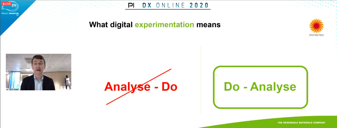
Jaswinder: The mistake of doing too much analysis paralyzed the organization. Sometimes you need to move ahead and adapt during the journey – do not wait. Sometimes there is too much focus on the quality of a business solution and not enough attention to the flow of information
Eric: COVID-19 was THE success. It pushed people to work with digital tools. They had immediately proof points delivering a deal within 6 weeks.
Samuli: The success is in funding ideas. Samuli had a more extended session on this topic during the event. Do not invest in long time projects – visible success is needed in a few months, not in 1 year.
Probably I liked these three pieces of advice so much as it is the same as what I am advising companies. Moving from a traditional PLM-approach towards a more model-based approach. Instead of waiting and looking till others master this topic, start learning (small) and make sure you make progress. Learning is crucial for a digital transformation in the PLM-domain.
What is Stopping Manufacturers from Implementing Industry 4.0
 This roundtable session was structured by Gavin Hill and Jonathan Bray, both from the AMRC (Advanced Manufacturing Research Centre), who gave several insights and examples from what AMRC has been doing as research in the context of Industry 4.0.
A roundtable is supposed to be an interactive session, which would have been a challenge as I noticed 49 people subscribed to this session. However, during the session, it became clear there was a significant silent majority.
Gavin and Jonathan had a lot to share. When the time came to interact with the audience, it was mostly other vendors talking about their Industry 4.0 vision or capabilities.
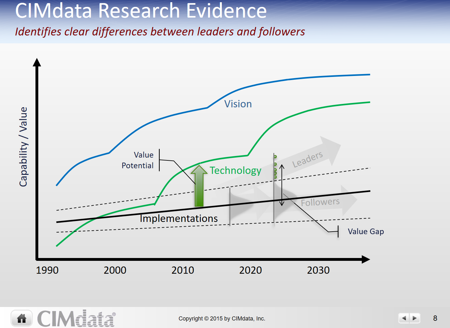 Vendors are perhaps more than ten years ahead with their vision as CIMdata’s image on the left states. When you would implement all these beautiful concepts, you will discover many frustrating gaps as your existing company’s processes, people, and skills are not that easy to change.
Smart Manufacturing: Simulating Workflows to Drive Efficiency and Productivity
![]() A company that has been active in Smart Manufacturing is AGCO, who has been presenting several times their future strategy and lessons learned at PI.
A company that has been active in Smart Manufacturing is AGCO, who has been presenting several times their future strategy and lessons learned at PI.
See Susan Lauda’s presentation in The weekend after PLMx Hamburg 2018
In this session, Andreas Frank and Dominik Hammerl shared how AGCO utilizes line balancing simulation to identify bottlenecks and create a productive, efficient workflow as one of the projects within their Smart Factory strategy.
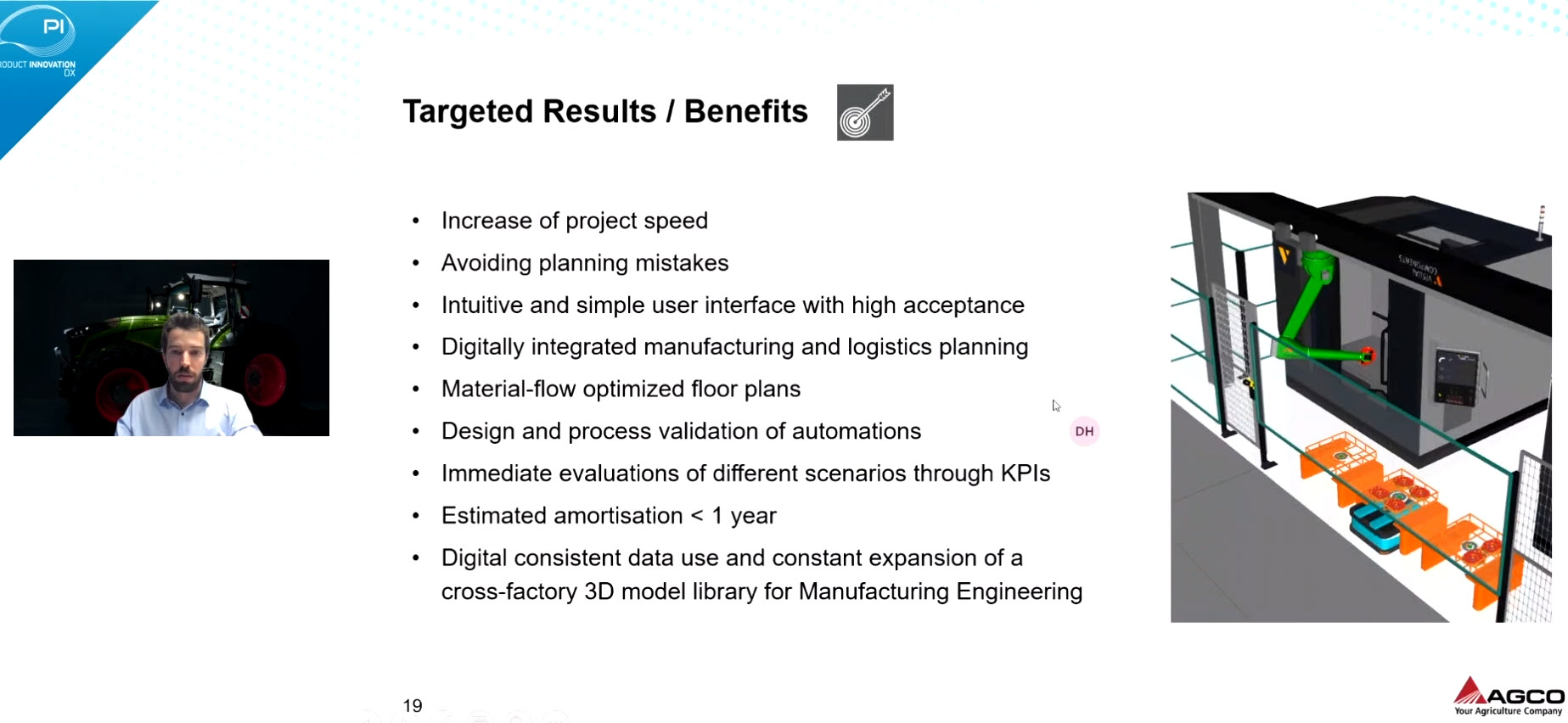 Their current solution was introducing a new that that had fast user adoption. The big elephant in the room remains to connect all these tools, having a flow of consistent data between all enterprise systems.
No problem at this time, as I heard in most of the sessions that I attended – stop analyzing and solving all the details upfront – start doing and learning – keeping the ultimate vision in mind/
Transforming to a Software-Centric Business Model: How the Need for Data is Changing Business
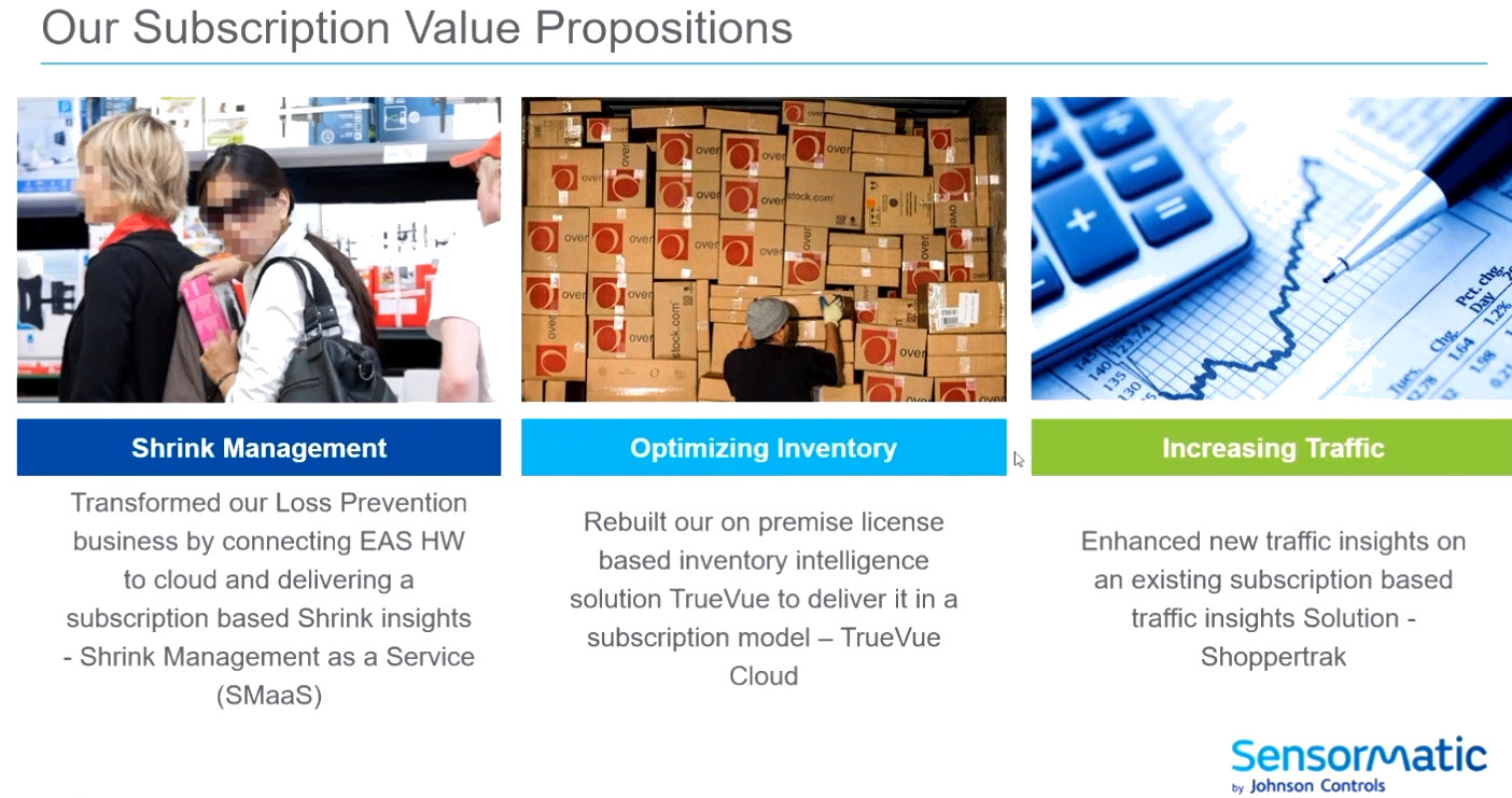
 This was an exciting session to see digital transformation in action. Subramanian Kunchithapatham, VP Engineering of Sensormatic Solutions (Johnson Controls) who are focusing on the brick and mortar retail shops.
These shops have been evolving as online shopping. The shift of focus towards customer experience in the shop requires these businesses to adapt. By using a digital twin concept for shop behavior and operations, they can now sell software solutions that improve their customer’s performance, as you can see from the image below.
To What Degree Do We Need To Integrate PLM, ERP and MES?
 This roundtable session, excellently moderated by Jan Johansson, Senior Director Digital Transformation at Terma A/S, was the type of roundtable you would like to participate in. I think the theme is actual for all of us
Statements varied from”ERP is our only system of truth as here we manage our financial execution” till”We should include CRM, CPQ and all other TLAs inside an enterprise – the connected enterprise”
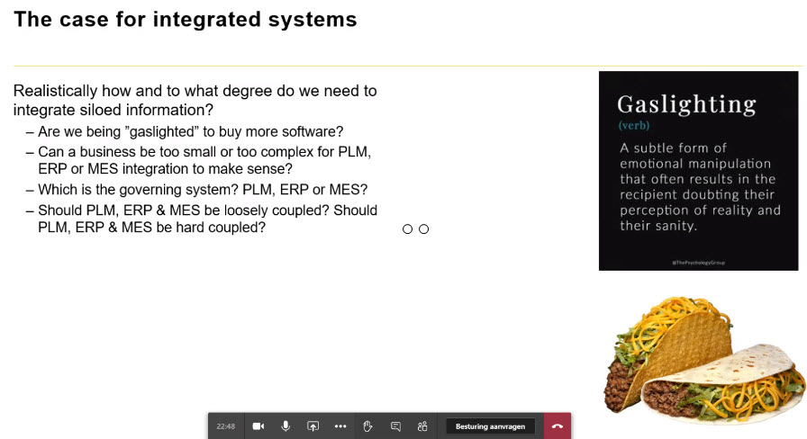
My observation was that many of us are still thinking in systems, an ERP-system, a PLM-system. We talk about”owning data” instead of”being accountable” for data in that context.
Another observation was to check who is responsible for PLM in your company. If it is engineering, probably your PLM-system is considered an engineering tool, not an infrastructure that enables product data to be available along the product lifecycle.
 How to deal with legacy data, a challenge in the aerospace industry. Store data in neutral formats or select a preferred vendor-related format and stick to it.
A great roundtable that hopefully inspired the participants to explore some of the options discussed or connect and learn more from each other experiences.
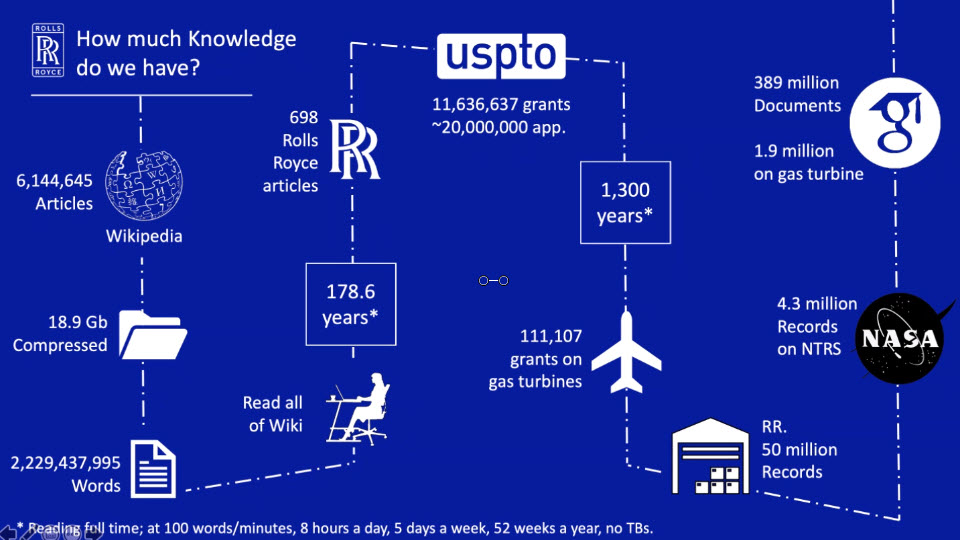
Overcoming Data Management Challenges with AI
 Nicely complementary to the previous roundtable was the session moderated by Mo (Muhannad)Alomari’s, AI Hub Lead at Rolls Royce plc. As an introduction, Mo dazzled us with the amount of data/knowledge related to gas turbines. Impossible to comprehend or access by human beings without the support of Artificial Intelligence.
Mo also brought the knowledge graph to our attention through this movie from the Google Knowledge Graph. We discussed this concept and its applicability for the PLM-domain. For sure, technology can bring high value for discovering information. However, there will still be a human-based interpretation required to filter out incorrect or unwanted associations. I think we all observe the challenges introduced by the”knowledge” algorithms on social media. Instead of building your knowledge, they try to drag you into even more absurd “facts.”
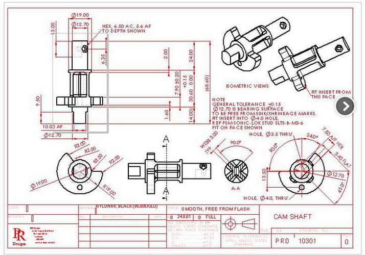 Mo also shared how, through AI, they are setting up data conversion practices. As you can imagine, a lot of Rolls Royce legacy data came from the era of paper/scanned drawings. Which text is meaningful on a drawing. Is the text a remark or an official annotation? AI-based best practices are not yet affordable for mainstream companies.
I believe we are all looking forward to learning from the best and bad practices of these frontrunners. As the group was small, it was an interesting discussion and learning session that you only can have by participating actively.
Embracing Digital in Face of Pandemic Disruption
 I want to close my highlights by pointing to the final panel discussion. Where the theme was to”hear from experts who have been guiding customers through digital transformation projects before COVID-19 and supporting their clients throughout the crisis,” you would expect an expert discussion.
 Indeed, the first part illustrated the trend that COVID-19 accelerated the focus on an inclusive and flexible supply chain. Perhaps traditional PLM-systems have a massive engineering focus, now most panelists report a shifted focus to the supply chain. The point of gravity has shifted.
The discussion started to shift, where the newcomers in PLM started to claim that they do not have an upgrade issue thanks to their cloud offering. An when Paul Powers started to pitch that upgrades should be as easy as smartphone upgrades and BOM-updates do not need people anymore because we have machine learning, it reminded me of my 2015 PDT presentation.
 In The Perfect Storm or a Fatal Tsunami session (here on Slideshare) , I predicted that AI and machine learning would remove many traditional PLM-related processes in the long-term. However, the future solutions must be rigid, not just a demo.
The discussion drifted toward “openness” and “PLM is dying out.” Again, here you could see the vendors’ fixation to talk about a single tool, not about a business strategy.
A statement like “PLM sucks” does not help the strategy. It shows these vendors cannot understand the PLM domain and prefer to create their own terminology, cornering PLM in the mechanical domain to be different. I will not go into the PLM sucks discussion as I mentioned this acronym at the PI 2016 event in Munich (slideshare).
However, we should be grateful that these companies sponsored this event. They imagine the (their) ideal future and thanks to their contribution, we were able to be in this event with fruitful discussions. Therefore my thanks to all the sponsors making this event happen.The challenge is always to imagine the future and next have a realistic path to get there on-time.
Conclusion
It was exciting to participate in this PI DX event. The Marketkey-team has transposed the conference concept to a virtual event, very close to the physical event. In particular, well-moderated roundtable sessions based on Teams are the big differentiator for me compared to other virtual events I have seen.
Expecting COVID-19 will not disappear next week, I look forward to the next event with such an interaction.
 This time it is again about learning. Last week, I read John Stark’s book: Products2019: A project to map and blueprint the flow and management of products across the product lifecycle: Ideation; Definition; Realisation; Support of Use; Retirement and Recycling. John, a well-known PLM consultant and writer of academic books related to PLM, wrote this book during his lockdown due to the COVID-19 virus. The challenge with PLM (books) is that it is, in a way boring from the outside. Remember my post: How come PLM and CM are boring? (reprise) ?
This time John wrapped the “boring” part into a story related to Jane from Somerset, who, as part of her MBA studies, is performing a research project for Josef Mayer Maschinenfabrik. The project is to describe for the newly appointed CEO what happens with the company’s products all along the lifecycle.

A story with a cliffhanger:
What happened to Newt from Cleveland?
Seven years in seven weeks
 Poor Jane, in seven weeks, she is interviewing people on three sites. Two sites in Germany and one in France, and she is doing over a hundred interviews on her own. I realized that thanks to relation to SmarTeam at that time, it took me probably seven years to get in front of all these stakeholders in a company.
I had much more fun most of the time as you can see below. My engagements were teamwork, where you had some additional social relief after work. Jane works even at the weekends.
![]() However, there are also many similarities. Her daily rhythm during working days. Gasthaus Adler reflects many of the typical guesthouses that I have visited. People staying there with a laptop were signs of the new world. Like Jane, I enjoyed the weissbier and noticed that sometimes overhearing other guests is not good for their company’s reputation. A lot of personal and human experiences are wrapped into the storyline.
However, there are also many similarities. Her daily rhythm during working days. Gasthaus Adler reflects many of the typical guesthouses that I have visited. People staying there with a laptop were signs of the new world. Like Jane, I enjoyed the weissbier and noticed that sometimes overhearing other guests is not good for their company’s reputation. A lot of personal and human experiences are wrapped into the storyline.
Spoiler: Tarzan meets Jane!
Cultural differences
 The book also illustrates the cultural difference between countries (Germany/France/US) nicely and even between regions (North & South). Just check the breakfast at your location to see it.
Although most of the people interviewed by Jane contributed to her research, she also meets that either for personal or political reasons, do not cooperate.
Having worked worldwide, including in Asian countries, I learned that understanding people and culture is crucial for successful PLM engagements.
 John did an excellent job of merging cultural and human behavior in the book. I am sure we share many similar experiences, as both this book and my blog posts, do not mention particular tools. It is about the people and the processes.
Topics to learn
![]() You will learn that 3D CAD is not the most important topic, as perhaps many traditional vendor-related PDM consultants might think.
You will learn that 3D CAD is not the most important topic, as perhaps many traditional vendor-related PDM consultants might think.
Portfolio Management is a topic well addressed. In my opinion, to be addressed in every PLM roadmap, as here, the business goals get connected to the products.
New Product Introduction, a stage-gate governance process, and the importance of Modularity are also topics that pop up in several cases.
The need for innovation, Industry 4.0 and AI (Artificial Intelligene) buzz, the world of software development and the “War for Talent” can all be found in the book.
 And I was happy that even product Master Data Management was addressed. In my opinion, not enough companies realize that a data-driven future requires data quality and data governance. I wrote about this topic last year: PLM and PIM – the complementary value in a digital enterprise.
There are fantastic technology terms, like APIs, microservices, Low Code platforms. They all rely on reliable and sharable data.
What’s next
Products2019 is written as the starting point for a sequel. In this book, you quickly learn all the aspects of a linear product lifecycle, as the image below shows

I see an opportunity for Products2020 (or later). What is the roadmap for a company in the future?
 How to deal with more data-driven, more agile in their go-to-market strategy, as software, will be more and more defining the product’s capabilities?
How to come from a linear siloed approach towards a horizontal flow of information, market-driven and agile?
Perhaps we will learn what happened with Newt from Cleveland?
Meanwhile, we have to keep on learning to build the future.
 My learning continues this week with PI DX USA 2020. Usually, a conference I would not attend as traveling to the USA would have too much impact on my budget and time. Now I can hopefully learn and get inspired – you can do the same! Feel free to apply for a free registration if you are a qualified end-user – check here.
And there is more to learn, already mentioned in my previous post:
- November 4th, the DigitalTwin Conference in the Netherlands – a one day conference in the Central European Timezone – mainly virtual, there will be a small local audience
- November 17-18-19, the CIMdata PLM Road Map & PDT Fall 2020 conference – entirely virtual with short Q&A sessions, targeting both the European as American timezone.
Conclusion
John Stark wrote a great book to understand what is currently in most people’s heads in mid-size manufacturing companies. If you are relatively new to PLM, or if you have only been active in PDM, read it – it is affordable! With my series Learning from the past, I also shared twenty years of experience, more a quick walkthrough, and a more specialized view on some of the aspects of PLM. Keep on learning!
![]() After the series about “Learning from the past,” it is time to start looking toward the future. I learned from several discussions that I probably work most of the time with advanced companies. I believe this would motivate companies that lag behind even to look into the future even more.
After the series about “Learning from the past,” it is time to start looking toward the future. I learned from several discussions that I probably work most of the time with advanced companies. I believe this would motivate companies that lag behind even to look into the future even more.
If you look into the future for your company, you need new or better business outcomes. That should be the driver for your company. A company does not need PLM or a Digital Twin. A company might want to reduce its time to market and improve collaboration between all stakeholders. These objectives can be realized by different ways of working and an IT infrastructure to allow these processes to become digital and connected.
 That is the “game”. Coming back to the future of PLM. We do not need a discussion about definitions; I leave this to the academics and vendors. We will see the same applies to the concept of a Digital Twin.
My statement: The digital twin is not new. Everybody can have their own digital twin as long as you interpret the definition differently. Does this sound like the PLM definition?
The definition
I like to follow the Gartner definition:
A digital twin is a digital representation of a real-world entity or system. The implementation of a digital twin is an encapsulated software object or model that mirrors a unique physical object, process, organization, person, or other abstraction. Data from multiple digital twins can be aggregated for a composite view across a number of real-world entities, such as a power plant or a city, and their related processes.
As you see, not a narrow definition. Now we will look at the different types of interpretations.
Single-purpose siloed Digital Twins
- Simple – data only
 One of the most straightforward applications of a digital twin is, for example, my Garmin Connect environment. My device registers performance parameters (speed, cadence, power, heartbeat, location) when cycling. Then, after every trip, I can analyze my performance. I can see changes in my overall performance; compare my performance with others in my category (weight, age, sex).
Based on that, I can decide if I want to improve my performance. My personal business goal is to maintain and improve my overall performance, knowing I cannot stop aging by upgrading my body.
On November 4th, 2020, I am participating in the (almost virtual) Digital Twin conference organized by Bits&Chips in the Netherlands. In the context of human performance, I look forward to Natal van Riel’s presentation: Towards the metabolic digital twin – for sure, this direction is not simple. Natal is a full professor at the Technical University in Eindhoven, the “smart city” in the Netherlands.
- Medium – data and operating models
 Many connected devices in the world use the same principle. An airplane engine, an industrial robot, a wind turbine, a medical device, and a train carriage; all track the performance based on this connection between physical and virtual, based on some sort of digital connectivity.
The business case here is also monitoring performance, predicting maintenance, and upgrading the product when needed.
 This is the domain of Asset Lifecycle Management, a practice that has existed for decades. Based on financial and performance models, the optimal balance between maintaining and overhauling has to be found. Repairs are disruptive and can be extremely costly. A manufacturing site that cannot produce can cost millions per day. Connecting data between the physical and the virtual model allows us to have real-time insights and be proactive. It becomes a digital twin.
- Advanced – data and connected 3D model
 The digital twin we see the most in marketing videos is a virtual twin, using a 3D representation for understanding and navigation. The 3D representation provides a Virtual Reality (VR) environment with connected data. When pointing at the virtual components, information might appear, or some animation might take place.
Building such a virtual representation is a significant effort; therefore, there needs to be a serious business case.
The simplest business case is to use the virtual twin for training purposes. A flight simulator provides a virtual environment and behavior as-if you are flying in a physical airplane – the behavior model behind the simulator should match as well as possibly the real behavior. However, as it is a model, it will never be 100 % reality and requires updates when new findings or product changes appear.
 A virtual model of a platform or plant can be used for training on Standard Operating Procedures (SOPs). In the physical world, there is no place or time to conduct such training. Here the complexity might be lower. There is a 3D Model; however, serious updates can only be expected after a major maintenance or overhaul activity.
These practices are not new either and are used in places where physical training cannot be done.
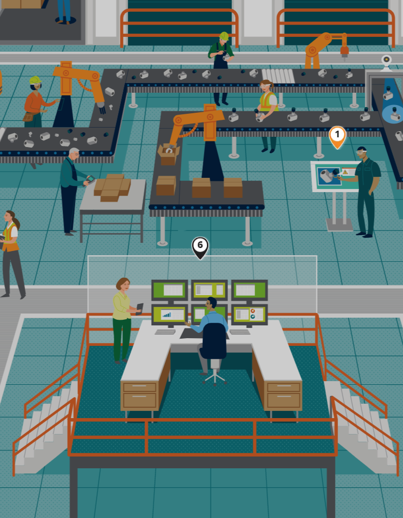
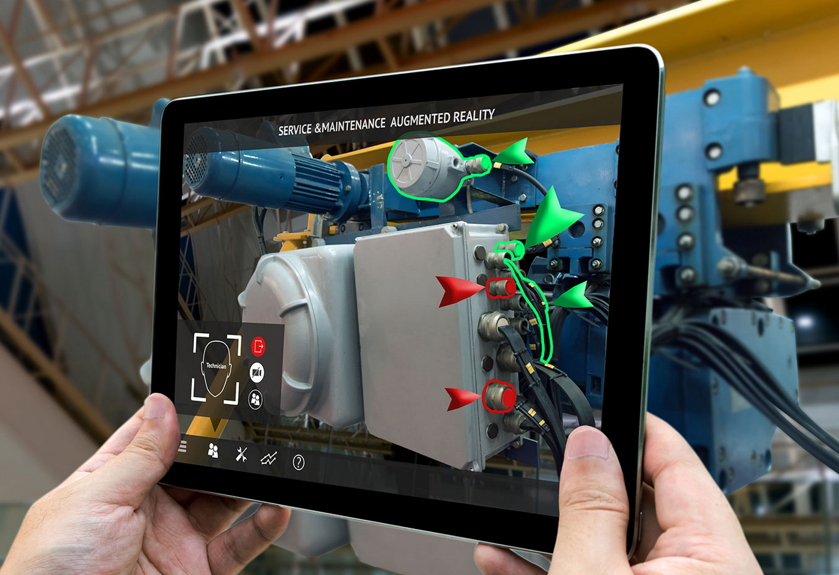 More challenging is the Augmented Reality (AR) use case. Here the virtual model, most of the time, a lightweight 3D Model, connects to real-time data coming from other sources. For example, AR can be used when an engineer has to service a machine. The AR environment might project actual data from the machine, indicate service points and service procedures.
The positive side of the business case is clear for such an opportunity, ensuring service engineers always work with the right information in a real-time context. The main obstacle to implementing AR, in reality, is the access to data, the presentation of the data and keeping the data in the AR environment matching the reality.
![]() And although there are 3D Models in use, they are, to my knowledge, always created in siloes, not yet connected to their design sources. Have a look at the Digital Twin conference from Bits&Chips, as mentioned before.
And although there are 3D Models in use, they are, to my knowledge, always created in siloes, not yet connected to their design sources. Have a look at the Digital Twin conference from Bits&Chips, as mentioned before.
Several of the cases mentioned above will be discussed here. The conference’s target is to share real cases concluded by Q & A sessions, crucial for a virtual event.
Connected Virtual Twins along the product lifecycle
So far, we have been discussing the virtual twin concept, where we connect a product/system/person in the physical world to a virtual model. Now let us zoom in on the virtual twins relevant for the early parts of the product lifecycle, the manufacturing twin, and the development twin. This image from Siemens illustrates the concept:
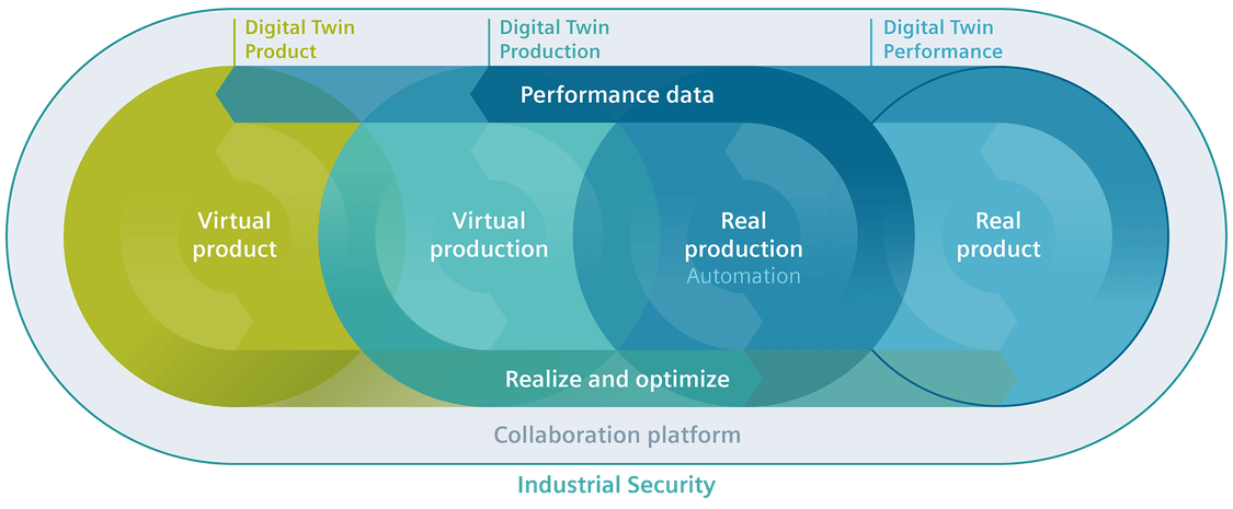
On slides they imagine a complete integrated framework, which is the future vision. Let us first zoom in on the individual connected twins.
The digital production twin
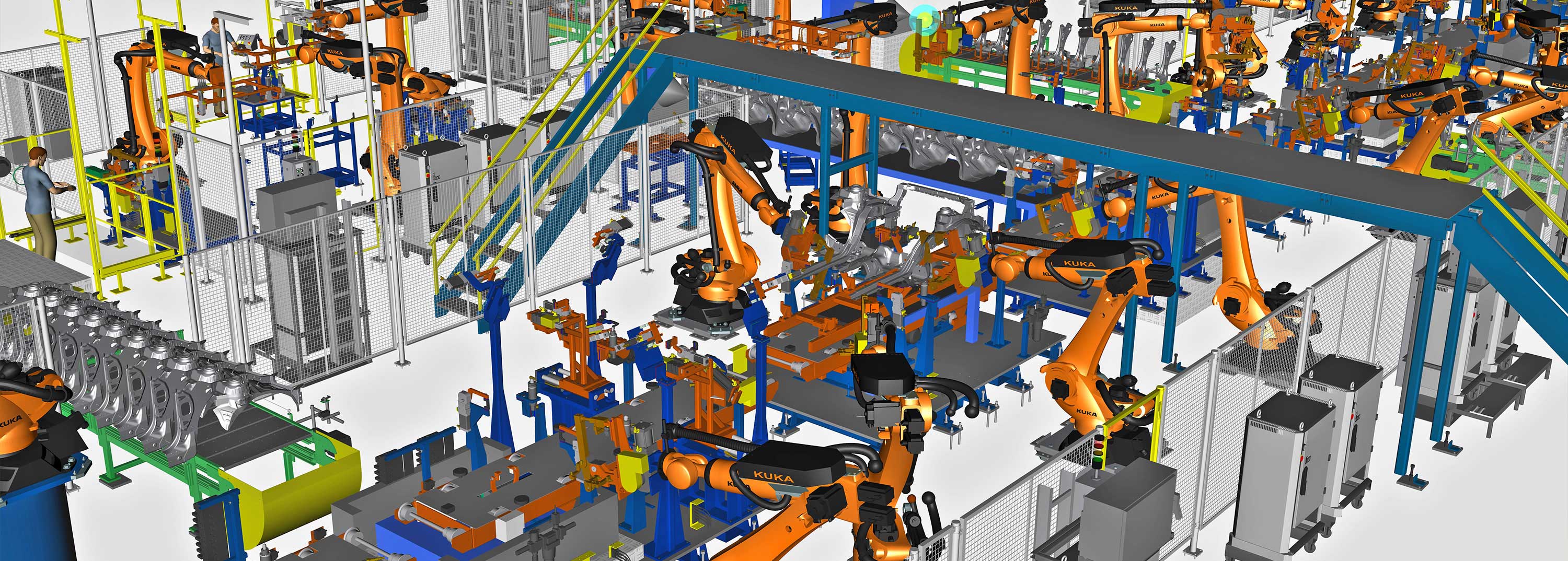 This is the area of virtual manufacturing and creating a virtual model of the manufacturing plant. Virtual manufacturing planning is not a new topic. DELMIA (Dassault Systèmes) and Tecnomatix (Siemens) are already for a long time offering virtual manufacturing planning solutions.
At that time, the business case was based on the fact that the definition of a manufacturing plant and process done virtually allows you to optimize the plant before investing in physical assets.
 Saving money as there is no costly prototype phase to optimize production. In a virtual world, you can perform many trade-off studies without extra costs. That was the past (and, for many companies, still the current situation).
With the need to be more flexible in manufacturing to address individual customer orders without increasing the overhead of delivering these customer-specific solutions, there is a need for a configurable plant that can produce these individual products (batch size 1).
 This is where the virtual plant model comes into the picture again. Instead of having a virtual model to define the ultimate physical plant, now the virtual model remains an active model to propose and configure the production process for each of these individual products in the physical plant.
This is partly what Industry 4.0 is about. Using a model-based approach to configure the plant and its assets in a connected manner. The digital production twin drives the execution of the physical plant. The factory has to change from a static factory to a dynamic “smart” factory.
In the domain of Industry 4.0, companies are reporting progress. However, in my experience, the main challenge is still that the product source data is not yet built in a model-based, configurable manner. Therefore, requires manual rework. This is the area of Model-Based Definition, and I have been writing about this aspect several times. Latest post: Model-Based: Connecting Engineering and Manufacturing
 The business case for this type of digital twin, of course, is to be able to customer-specific products with extremely competitive speed and reduced cost compared to standard. It could be your company’s survival strategy. As it is hard to predict the future, as we see from COVID-19, it is still crucial to anticipate the future instead of waiting.
The digital development twin
 Before a product gets manufactured, there is a product development process. In the past, this was pure mechanical with some electronic components. Nowadays, many companies are actually manufacturing systems as the software controlling the product plays a significant role. In this context, the model-based systems engineering approach is the upcoming approach to defining and testing a system virtually before committing to the physical world.
 Model-Based Systems Engineering can define a single complex product and perform all kinds of analyses on the system even before there is a physical system in place. I will explain more about model-based systems engineering in future posts. In this context, I want to stress that having a model-based system engineering environment combined with modularity (do not confuse it with model-based) is a solid foundation for dealing with unique custom products. Solutions can be configured and validated against their requirements already during the engineering phase.
 The business case for the digital development twin is easy to make. Shorter time to market, improved and validated quality, and reduced engineering hours and costs compared to traditional ways of working. To achieve these results, for sure, you need to change your ways of working and the tools you are using. So it won’t be that easy!
 For those interested in Industry 4.0 and the Model-Based System Engineering approach, join me at the upcoming PLM Road Map 2020 and PDT 2020 conference on 17-18-19 November. As you can see from the agenda, a lot of attention to the Digital Twin and Model-Based approaches.
Three digital half-days with hopefully a lot to learn and stay with our feet on the ground. In particular, I am looking forward to Marc Halpern’s keynote speech: Digital Thread: Be Careful What you Wish For, It Just Might Come True
Conclusion
It has been very noisy on the internet related to product features and technologies, probably due to COVID-19 and therefore disrupted interactions between all of us – vendors, implementers and companies trying to adjust their future. The Digital Twin concept is an excellent framing for a concept that everyone can relate to. Choose your business case and then look for the best matching twin.
 On March 22 this year, I wrote Time to Think (and act differently) in de middle of a changing world. We were entering a lockdown in the Netherlands due to the COVID-19 virus. As it was such a disruptive change, it was an opportunity to adapt their current ways of working.
The reason for that post was my experience when discussing PLM-initiatives with companies. Often they have no time to sit down, discuss and plan their PLM targets as needed. Crucial people are too busy, leading to an implementation of a system that, in the best case, creates (some) benefits.
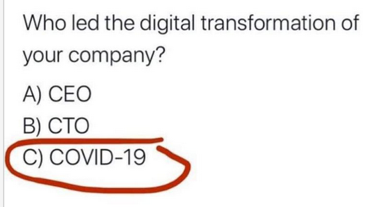
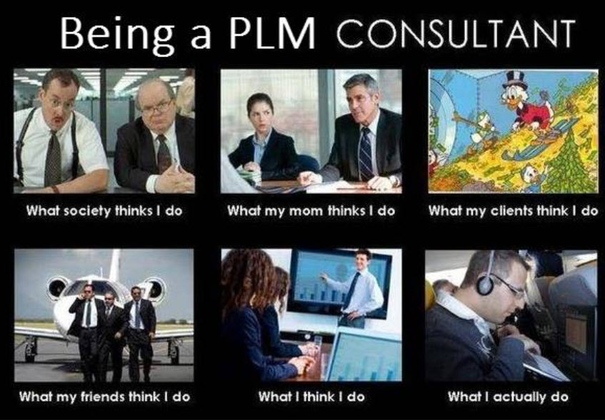
 The well-known cartoon says it all. We are often too busy doing business as usual, making us feel comfortable. Only when it is too late, people are forced to act. As the second COVID-19 wave seems to start in the Netherlands, I want to look back on what has happened so far in my eco-system.
Virtual Conferences
As people could not travel anymore, traditional PLM-conferences could not be organized anymore. What was going to be the new future for conferences? TECHNIA, apparently clairvoyant, organized their virtual PLM Innovation Forum as one of the first, end of April.

A more sustainable type of PLM-conference was already a part of their plans, given the carbon footprint a traditional conference induces. The virtual conference showed that being prepared for a virtual conference pays off during a pandemic with over 1000 participants.
Being first does not always mean being the best, as we have to learn. While preparing my session for the conference, I felt the same excitement as for a traditional conference. You can read about my initial experience here: The weekend after the PLM Innovation Forum.
Some weeks later, having attended some other virtual conferences, I realized that some points should be addressed/solved:
- Video conferencing is a must – without seeing people talking, it becomes a podcast.
- Do not plan long conference days. It is hard to sit behind a screen for a full day. A condensed program makes it easier to attend.
- Virtual conferences mean that they can be attended live from almost all around the globe. Therefore, finding the right timeslots is crucial for the audience – combined with the previous point – shorter programs.
- Playing prerecorded sessions without a Q&A session should be avoided. It does not add value.
- A conference is about networking and discussion – I have not seen a solution for this yet. Fifty percent of the conference value for me comes from face-to-face discussions and coffee meetings. A virtual conference needs to have private chat opportunities between attendees.
In the last quarter of this year, I will present at several merely local conferences, sometimes a mix between “live” with a limited number of attendees, if it will be allowed.
And then there is the upcoming PLM Road Map & PDT Fall 2020 (virtual) conference on 17-18-19 November.

This conference has always been my favorite conference thanks to its continued focus on sharing experiences, most of the time, based on industry standards. We discuss topics and learn from each other. See my previous posts: The weekend after 2019 Day 1, 2019 Day 2, 2018 Day 1, 2018 Day2, 2017 Day 1, 2017 Day 2, etc.
The theme Digital Thread—the PLM Professionals’ Path to Delivering Innovation, Efficiency, and Quality has nothing to do with marketing. You can have a look at the full schedule here. Although there is a lot of buzz around Digital Thread, presenters discuss the reality and their plans
Later in this post, see the paragraph Digital Thread is not a BOM, I will elaborate on this theme.
Getting tired?
 I discovered I am getting tired as I am missing face-to-face interaction with people. Working from home, having video calls, is probably a very sustainable way of working. However, non-planned social interaction, meeting each other at the coffee machine, or during the breaks at a conference or workshop, is also crucial for informal interaction.
Apparently, several others in my eco-system are struggling too. I noticed a tsunami of webinars and blog posts where many of them were an attempt to be noticed. Probably the same reason: traditionally businesses have stalled. And it is all about Digital Transformation and SaaS at this moment. Meaningless if there is no interaction.

My favorite quote:
I still meet people that continue to express beliefs about the world, their industry, their customers or their own performance that simply aren’t true. Although some, like Steve Jobs, were known for their “reality distortion field,” for virtually all of us, just wishing for something to be true doesn’t make it so. As William Edwards Deming famously said: in God we trust; all others must bring data.
I fully concur with this statement and always get suspicious when someone claims the truth.
Still, there are some diamonds.
I enjoyed all episodes from Minerva PLM TV – Jennifer Moore started these series in the early COVID19-days (coincidence?). She was able to have a collection of interviews with known and less-known people in the PLM-domain. As most of them were vendor-independent, these episodes are a great resource to get educated.

The last episode with Angela Ippisch illustrates how often PLM in companies depends on a few enthusiastic persons, who have the energy to educate themselves. Angela mentions there is a lot of information on the internet; the challenge is to separate the useful information from marketing.
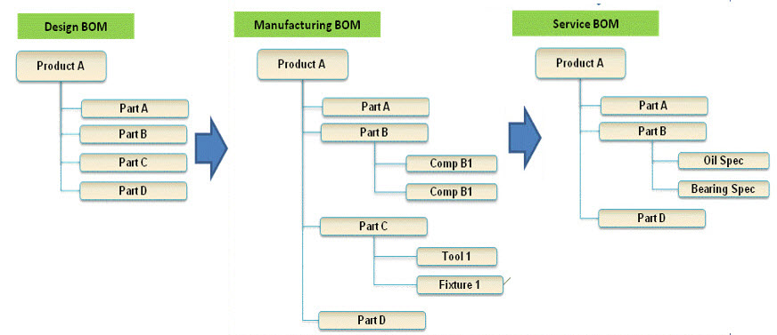
 I have been publishing the past five months a series of posts under the joint theme learning from the past to understand the future. In these posts, I explained the evolution from PDM to PLM, resulting in the current item-centric approach with an EBOM, MBOM, and SBOM.
On purpose, one post per every two weeks – to avoid information overflow. Looking back, it took more posts than expected, and they are an illustration of the many different angles there are in the PLM domain – not a single truth.
Digital Thread is not a BOM
I want to address this point because I realized that in the whole blogging world there appear to be two worlds when discussing PLM terminology. Oleg Shilovitsky, CEO@OpenBOM, claims that Digital Thread and Digital Twin topics are just fancy marketing terms. I was even more surprised to read his post: 3 Reasons Why You Should Avoid Using The Word “Model” In PLM. Read the comments and discussion in these posts (if LinkedIn allows you to navigate)
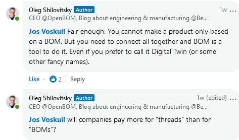
![]() Oleg’s posts have for me most of the time, always something to discuss. I would be happier if other people with different backgrounds would participate in these discussions too – A “Like” is not a discussion. The risk in a virtual world is that it becomes a person-to-person debate, and we have seen the damage such debates can do for an entire community.
Oleg’s posts have for me most of the time, always something to discuss. I would be happier if other people with different backgrounds would participate in these discussions too – A “Like” is not a discussion. The risk in a virtual world is that it becomes a person-to-person debate, and we have seen the damage such debates can do for an entire community.
In the discussion we had related to Digital Thread and BOM, I realized that when we talk about traditional products, the BOM and the Digital Thread might be the same. This is how we historically released products to the market. Once produced, there were no more changes. In these situations, you could state a PLM-backbone based on BOM-structures/views, the EBOM, MBOM, and SBOM provide a Digital Thread.
The different interpretation comes when talking about products that contain software defining its behavior. Like a computer, the operating system can be updated on the fly; meanwhile, the mechanical system remains the same. To specify and certify the behavior of the computer, we cannot rely on the BOM anymore.
Having software in the BOM and revise the BOM every time there is a software change is a mission impossible. A mistake suggested ten years ago when we started to realize the different release cycles of hardware and software. Still, it is all about the traceability of all information related to a product along its whole lifecycle.
 In a connected environment, we need to manage relationships between the BOM and relations to other artifacts. Managing these relations in a connected environment is what I would call the Digital Thread – a layer above PLM. While writing this post, I saw Matthias Ahrens’ post stating the same (click on the image to see the post)
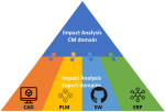 When we discuss managing all the relations, we touch the domain of Configuration Management. Martijn Dullaart/Martin Haket’s picture shares the same mindset – here, CM is the overlapping layer.
However, in their diagram, it is not a system picture; the different systems do not need to be connected. Configuration Management is the discipline that maintains the correct definition of every product – CM maintains the Thread. When it becomes connected, it is a Digital Thread.
As I have reached my 1500 words, I will not zoom in on the PLM and Model discussion – build your opinion yourself. We have to realize that the word Model always requires a context. Perhaps many of us coming from the traditional PDM/PLM world (managing CAD data) think about CAD models. As I studied physics before even touching CAD, I grew up with a different connotation
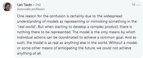 Lars Taxén’s comment in this discussion perhaps says it all (click on the image to read it). If you want to learn and discuss more about the Digital Thread and Models, register for the PLM Roadmap & PDT2020 event as many of the sessions are in this context (and not about 3D CAD).
Conclusion
I noticed I am getting tired of all the information streams crying for my attention and look forward to real social discussions, not broadcasted. Time to think differently requires such discussion, and feel free to contact me if you want to reflect on your thoughts. My next action will be a new series named Painting the future to stay motivated. (As we understand the past).
 In the previous seven posts, learning from the past to understand the future, we have seen the evolution from manual 2D drawing handling. Next, the emerge of ERP and CAD followed by data management systems (PDM/PLM) and methodology (EBOM/MBOM) to create an infrastructure for product data from concept towards manufacturing.
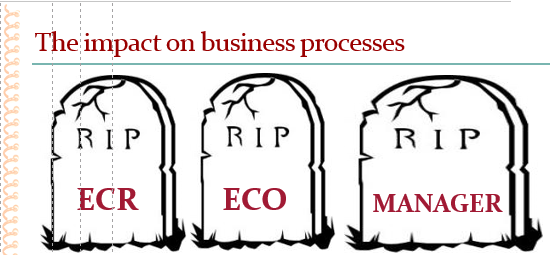
Before discussing the extension to the SBOM-concept, I first want to discuss Engineering Change Management and Configuration Management.
ECM and CM – are they the same?
Often when you talk with people in my PLM bubble, the terms Change Management and Configuration Management are mixed or not well understood.
![]() When talking about Change Management, we should clearly distinguish between OCM (Organizational Change Management) and ECM (Engineering Change Management). In this post, I will focus on Engineering Change Management (ECM).
When talking about Change Management, we should clearly distinguish between OCM (Organizational Change Management) and ECM (Engineering Change Management). In this post, I will focus on Engineering Change Management (ECM).
When talking about Configuration Management also here we find two interpretations of it.
![]() The first one is a methodology describing technically how, in your PLM/CAD-environment, you can build the most efficient way connected data structures, representing all product variations. This technology varies per PLM/CAD-vendor, and therefore I will not discuss it here. The other interpretation of Configuration Management is described on Wiki as follows:
The first one is a methodology describing technically how, in your PLM/CAD-environment, you can build the most efficient way connected data structures, representing all product variations. This technology varies per PLM/CAD-vendor, and therefore I will not discuss it here. The other interpretation of Configuration Management is described on Wiki as follows:
Configuration management (CM) is a systems engineering process for establishing and maintaining consistency of a product’s performance, functional, and physical attributes with its requirements, design, and operational information throughout its life.
This is also the area where I will focus on this time.
And as-if great minds think alike and are synchronized, I was happy to see Martijn Dullaart’s recent blog post, referring to a poll and follow-up article on CM.

Here Martijn precisely touches the topic I address in this post. I recommend you to read his post: Configuration Management done right = Product-Centric first and then follow with the rest of this article.
Engineering Change Management
 Initially, engineering change management was a departmental activity performed by engineering to manage the changes in a product’s definition. Other stakeholders are often consulted when preparing a change, which can be minor (affecting, for example, only engineering) or major (affecting engineering and manufacturing).
The way engineering change management has been implemented varies a lot. Over time companies all around the world have defined their change methodology, and there is a lot of commonality between these approaches. However, terminology as revision, version, major change, minor change all might vary.

I described the generic approach for engineering change processes in my blog post: ECR / ECO for Dummies from 2010.
The fact that companies have defined their own engineering change processes is not an issue when it works and is done manually. The real challenge came with PDM/PLM-systems that need to provide support for engineering change management.
Do you leave the methodology 100 % open, or do you provide business logic?
 I have seen implementations where an engineer with a right-click could release an assembly without any constraints. Related drawings might not exist, parts in the assembly are not released, and more. To obtain a reliable engineering change management process, the company had to customize the PLM-system to its desired behavior.
An exercise excellent for a system integrator as there was always a discussion with end-users that do not want to be restricted in case of an emergency (“we will complete the definition later” / “too many clicks” / “do I have to approve 100 parts ?”). In many cases, the system integrator kept on customizing the system to adapt to all wishes. Often the engineering change methodology on paper was not complete or contained contradictions when trying to digitize the processes.
 For that reason, the PLM-vendors that aim to provide Out-Of-The-Box solutions have been trying to predefine certain behaviors in their system. For example, you cannot release a part, when its specifications (drawings/documents) are not released. Or, you cannot update a released assembly without creating a new revision.
These rules speed-up the implementation; however, they require more OCM (Organizational Change Management) as probably naming and methodology has to change within the company. This is the continuous battle in PLM-implementations. In particular where the company has a strong legacy or lack of business understanding, when implementing PLM.

There is an excellent webcast in this context on Minerva PLM TV – How to Increase IT Project Success with Organizational Change Management.
Click on the image or link to watch this recording.
Configuration Management
When we talk about configuration management, we have to think about managing the consistency of product data along the whole product lifecycle, as we have seen from the Wiki-definition before.

Wiki – the configuration Activity Model
Configuration management existed long before we had IT-systems. Therefore, configuration management is more a collection of activities (see diagram above) to ensure the consistency of information is correct for any given product. Consistent during design, where requirements match product capabilities. Consistent with manufacturing, where the manufacturing process is based on the correct engineering specifications. And consistent with operations, meaning that we have the full definition of product in the field, the As-Built, in correct relation to its engineering and manufacturing definition.

Source: Configuration management in aerospace industry
This consistency is crucial for products where the cost of an error can have a massive impact on the manufacturer. The first industries that invested heavily in configuration management were the Aerospace and Defense industries. Configuration management is needed in these industries as the products are usually complex, and failure can have a fatal impact on the company. Combined with many regulatory constraints, managing the configuration of a product and the impact of changes is a discipline on its own.

Other industries have also introduced configuration management nowadays. The nuclear power industry and the pharmaceutical industry use configuration management as part of their regulatory compliance. The automotive industry requires configuration management partly for compliance, mainly driven by quality targets. An accident or a recall can be costly for a car manufacturer. Other manufacturing companies all have their own configuration management strategies, mainly depending on their own risk assessment. Configuration management is a pro-active discipline – it costs money – time, people and potential tools to implement it. In my experience, many of these companies try to do “some” configuration management, always hoping that a real disaster will not happen (or can happen). Proper configuration management allows you to perform reliable impact analysis for any change (image above)
What happens in the field?
 When introducing PLM in mid-market companies, often, the dream was that with the new PLM-system configuration, management would be there too.
Management believes the tools will fix the issue.
Partly because configuration management deals with a structured approach on how to manage changes, there was always confusion with engineering change management. Modern PLM-systems all have an impact analysis capability. However, most of the time, this impact analysis only reaches the content that is in the PLM-system. Configuration Management goes further.
If you think that configuration management is crucial for your company, start educating yourselves first before implementing anything in a tool. There are several places where you can learn all about configuration management.
![]()
- Probably the best-known organization is IpX (Institute for Process Excellence), teaching the CM2 methodology. Have a look here: CM2 certification and courses
- Closely related to IpX, Martijn Dullaart shares his thoughts coming from the field as Lead Architect for Enterprise Configuration Management at ASML (one of the Dutch crown jewels) in his blog: MDUX
- CMstat, a configuration and data management solution provider, provides educational posts from their perspective. Have a look at their posts, for example, PLM or PDM or CM
- If you want to have a quick overview of Configuration Management in general, targeted for the mid-market, have a look at this (outdated) course: Training for Small and Medium Enterprises on CONFIGURATION MANAGEMENT. Good for self-study to get an understanding of the domain.
To summarize
 In regulated industries, Configuration Management and PLM are a must to ensure compliance and quality. Configuration management and (engineering) change management are, first of all, required methodologies that guarantee the quality of your products. The more complex your products are, the higher the need for change and configuration management.
PLM-systems require embedded engineering change management – part of the PDM domain. Performing Engineering Change Management in a system is something many users do not like, as it feels like overhead. Too much administration or too many mouse clicks.
So far, there is no golden egg that performs engineering change management automatically. Perhaps in a data-driven environment, algorithms can speed-up change management processes. Still, there is a need for human decisions.
Similar to configuration management. If you have a PLM-system that connects all the data from concept, design, and manufacturing in a single environment, it does not mean you are performing configuration management. You need to have processes in place, and depending on your product and industry, the importance will vary.
Conclusion
In the first seven posts, we discussed the design and engineering practices, from CAD to EBOM, ending with the MBOM. Engineering Change Management and, in particular, Configuration Management are methodologies to ensure the consistency of data along the product lifecycle. These methodologies are connected and need to be fit for the future – more on this when we move to modern model-based approaches.
Closing note:
 While finishing this blog post today I read Jan Bosch’s post: Why you should not align. Jan touches the same topic that I try to describe in my series Learning from the Past ….., as my intention is to make us aware that by holding on to practices from the past we are blocking our future. Highly recommended to read his post – a quote:
The problem is, of course, that every time you resist change, you get a bit behind. You accumulate some business, process and technical debt. You become a little less “fitting” to the environment in which you’re operating
 In the series learning from the past to understand the future, we have almost reached the current state of PLM before digitization became visible. In the last post, I introduced the value of having the MBOM preparation inside a PLM-system, so manufacturing engineering can benefit from early visibility and richer product context when preparing the manufacturing process.
Does everyone need an MBOM?
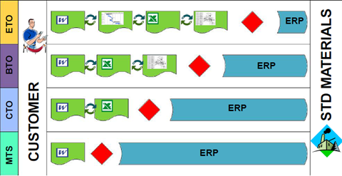 It is essential to realize that you do not need an EBOM and a separate MBOM in case of an Engineering To Order primary process. The target of ETO is to deliver a unique customer product with no time to lose. Therefore, engineering can design with a manufacturing process in mind.
The need for an MBOM comes when:
- You are selling a specific product over a more extended period of time. The engineering definition, in that case, needs to be as little as possible dependent on supplier-specific parts.
- You are delivering your portfolio based on modules. Modules need to be as long as possible stable, therefore independent of where they are manufactured and supplier-specific parts. The better you can define your modules, the more customers you can reach over time.
- You are having multiple manufacturing locations around the world, allowing you to source locally and manufacture based on local plant-specific resources. I described these options in the previous post
 The challenge for all companies that want to move from ETO to BTO/CTO is the fact that they need to change their methodology – building for the future while supporting the past. This is typically something to be analyzed per company on how to deal with the existing legacy and installed base.
Configurable EBOM and MBOM
In some previous posts, I mentioned that it is efficient to have a configurable EBOM. This means that various options and variants are managed in the same EBOM-structure that can be filtered based on configuration parameters (date effectivity/version identifier/time baseline). A configurable EBOM is often called a 150 % EBOM
 The MBOM can also be configurable as a manufacturing plant might have almost common manufacturing steps for different product variants. By using the same process and filtered MBOM, you will manufacture the specific product version. In that case, we can talk about a 120 % MBOM
Note: the freedom of configuration in the EBOM is generally higher than the options in the configurable MBOM.
The real business change for EBOM/MBOM
So far, we have discussed the EBOM/MBOM methodology. It is essential to realize this methodology only brings value when the organization will be adapted to benefit from the new possibilities. 
One of the recurring errors in PLM implementations is that users of the system get an extended job scope, without giving them the extra time to perform these activities. Meanwhile, other persons downstream might benefit from these activities. However, they will not complain. I realized that already in 2009, I mentioned such a case: Where is my PLM ROI, Mr. Voskuil?
Now let us look at the recommended business changes when implementing an EBOM/MBOM-strategy
- Working in a single, shared environment for engineering and manufacturing preparation is the first step to take.
Working in a PLM-system is not a problem for engineers who are used to the complexity of a PDM-system. For manufacturing engineers, a PLM-environment will be completely new. Manufacturing engineers might prepare their bill of process first in Excel and ultimately enter the complete details in their ERP-system. ERP-systems are not known for their user-friendliness. However, their interfaces are often so rigid that it is not difficult to master the process. Excel, on the other side, is extremely flexible but not connected to anything else.
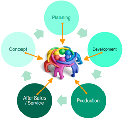 And now, this new PLM-system requires people to work in a more user-friendly environment with limited freedom. This is a significant shift in working methodology. This means manufacturing engineers need to be trained and supported over several months. Changing habits and keep people motivated takes energy and time. In reality, where is the budget for these activities? See my 2016 post: PLM and Cultural Change Management – too expensive?
- From sequential to concurrent
Once your manufacturing engineers are able to work in a PLM-environment, they are able to start the manufacturing definition before the engineering definition is released. Manufacturing engineers can participate in design reviews having the information in their environment available. They can validate critical manufacturing steps and discuss with engineers potential changes that will reduce the complexity or cost for manufacturing. As these changes will be done before the product is released, the cost of change is much lower. After all, having engineering and manufacturing working partially in parallel will reduce time to market.
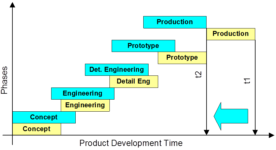
Reducing time to market by concurrent engineering
One of the leading business drivers for many companies is introducing products or enhancements to the market. Bringing engineering and manufacturing preparation together also means that the PLM-system can no longer be an engineering tool under the responsibility of the engineering department.
 The responsibility for PLM needs to be at a level higher in the organization to ensure well-balanced choices. A higher level in the organization automatically means more attention for business benefits and less attention for functions and features.
From technology to methodology – interface issues?
The whole EBOM/MBOM-discussion often has become a discussion related to a PLM-system and an ERP-system. Next, the discussion diverted to how these two systems could work together, changing the mindset to the complexity of interfaces instead of focusing on the logical flow of information.
 In an earlier PI Event in München 2016, I lead a focus group related to the PLM and ERP interaction. The discussion was not about technology, all about focusing on what is the logical flow of information. From initial creation towards formal usage in a product definition (EBOM/MBOM).
What became clear from this workshop and other customer engagements is that people are often locked in their siloed way of thinking. Proposed information flows are based on system capabilities, not on the ideal flow of information. This is often the reason why a PLM/ERP-interface becomes complicated and expensive. System integrators do not want to push for organizational change, they prefer to develop an interface that adheres to the current customer expectations.
SAP has always been promoting that they do not need an interface between engineering and manufacturing as their data management starts from the EBOM. They forgot to mention that they have a difficult time (and almost no intention) to manage the early ideation and design phase. As a Dutch SAP country manager once told me: “Engineers are resources that do not want to be managed.” This remark says all about the mindset of ERP.
After overlooking successful PLM-implementations, I can tell the PLM-ERP interface has never been a technical issue once the methodology is transparent. A company needs to agree on logical data flow from ideation through engineering towards design is the foundation.
 It is not about owning data and where to store it in a single system. It is about federated data sets that exist in different systems and that are complementary but connected, requiring data governance and master data management.
The SAP-Siemens partnership
In the context of the previous paragraph, the messaging around the recently announced partnership between SAP and Siemens made me curious. Almost everyone has shared an opinion about the partnership. There is a lot of speculation, and many questions were imaginarily answered by as many blog posts in the field. Last week Stan Przybylinski shared CIMdata’s interpretations in a webinar Putting the SAP-Siemens Partnership In Context, which was, in my opinion, the most in-depth analysis I have seen.
For what it is worth, my analysis:
- First of all, the partnership is a merger of slide decks at this moment, aiming to show to a potential customer that in the SAP/Siemens-combination, you find everything you need. A merger of slides does not mean everything works together.
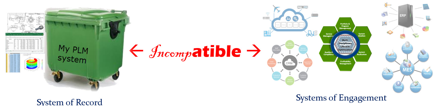
- It is a merger of two different worlds. You can call SAP a real data platform with connected data, where Siemens offering is based on the Teamcenter backbone providing a foundation for a coordinated approach. In the coordinated approach, the data flexibility is lower. For that reason, Mendix is crucial to make Siemens portfolio behave like a connected platform too.
You can read my doubts about having a coordinated and connected system working together (see image above). It was my #1 identified challenge for this decade: PLM 2020 – PLM the next decade (before COVID-19 became a pandemic and illustrated we need to work connected) - The fact that SAP will sell TC PLM and Siemens will sell SAP PPM seems like loser’s statement, meaning our SAP PLM is probably not good enough, or our TC PPM capabilities are not good enough. In reality, I believe they both should remain, and the partnership should work on logical data flows with data residing in two locations – the federated approach. This is how platforms reside next to each other instead of the single black hole.


- The fact that standard interfaces will be developed between the two systems is a subtle sales argument with relatively low value. As I wrote in the “from technology to methodology”-paragraph, the challenges are in the organizational change within companies. Technology is not the issue, although system integrators also need to make a living.
- What I believe makes sense is that both SAP and Siemens, have to realize their Industry 4.0 end-to-end capabilities. It is a German vision now for several years and it is an excellent vision to strive for. Now it is time to build the two platforms working together. This will be a significant technical challenge mainly for Siemens as its foundation is based on a coordinated backbone.
- The biggest challenge, not only for this partnership, is the organizational change within companies that want to build an end-to-end connected solution. In particular, in companies with a vast legacy, the targeted industries by the partnership, the chasm between coordinated legacy data and intended connected data is enormous. Technology will not fix it, perhaps smoothen the pain a little.

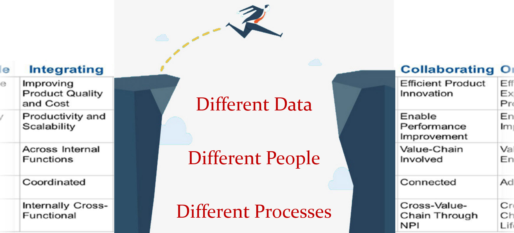
Conclusion
With this post, we have reached the foundation of the item-centric approach for PLM, where the EBOM and MBOM are managed in a real-time context. Organizational change is the biggest inhibitor to move forward. The SAP-Siemens partnership is a sales/marketing approach to create a simplified view for the future at C-level discussions.
Let us watch carefully what happens in reality.
Next time potentially the dimension of change management and configuration management in an item-centric approach.
Or perhaps Martijn Dullaart will show us the way before, following up on his tricky poll question
 Already five posts since we started looking at the roots of PLM, where every step illustrated that new technical capabilities could create opportunities for better practices. Alternatively, sometimes, these capabilities introduced complexity while maintaining old practices. Where the previous posts were design and engineering-centric, now I want to make the step moving to manufacturing-preparation and the MBOM. In my opinion, if you start to manage your manufacturing BOM in the context of your product design, you are in the scope of PLM.
For the moment, I will put two other related domains aside, i.e., Configuration Management and Configured Products. Note these domains are entirely different from each other.
Some data model principles
 In part five, I introduced the need to have a split between a logical product definition and a technical EBOM definition. The logical product definition is more the system or modular structure to be used when configuring solutions for a customer. The technical EBOM definition is, most of the time, a stable engineering specification independent of how and where the product is manufactured. The manufacturing BOM (the MBOM) should represent how the product will be manufactured, which can vary per location and vary over time. Let us look in some of the essential elements of this data model
The Product
 The logical definition of the product, which can also be a single component if you are a lower tier-supplier, has an understandable number, like 6030-10B. A customer needs to be able to order this product or part without a typo mistake. The product has features or characteristics that are used to sell the product. Usually, products do not have a revision, as it is a logical definition of a set of capabilities. Most of the time, marketing is responsible for product definition. This would be the sales catalog, which can be connected in a digital PLM environment. Like the PDM-ERP relation, there is a similar discussion related to where the catalog resides—more on the product side later in time.
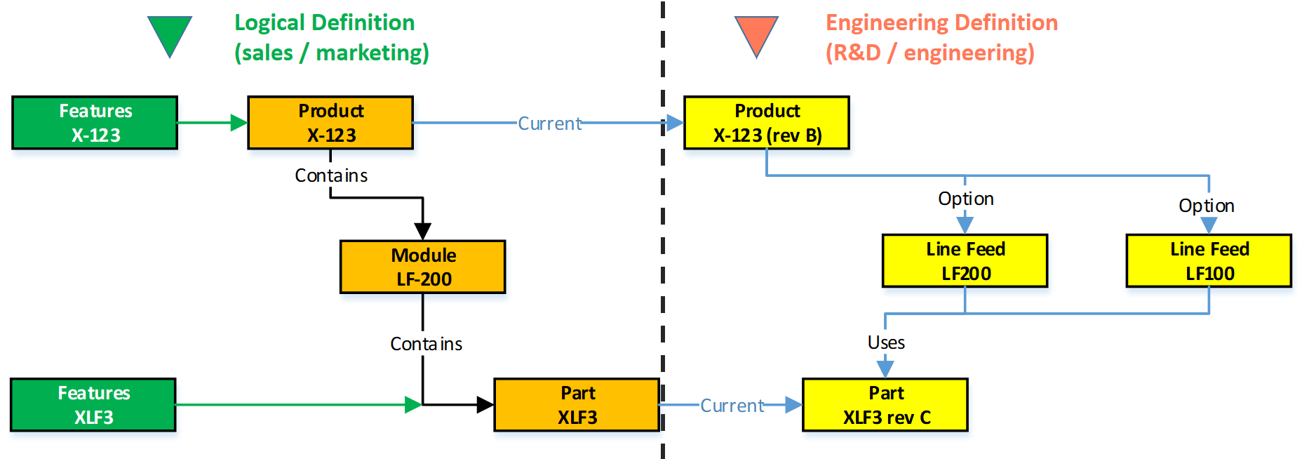
The EBOM
Related to the product or component in the logical definition, there is an actual EBOM, which represents the technical specification of the product. The image above shows the relation represented by the blue “current” link.
 Note: not all systems will support such a data model, and often the marketing sides in managed disconnected from the engineering side. Either in Excel or in a specialized Product Line Engineering (PLE) tools.
We discussed in the previous post that if you want to minimize maintenance, meaning fewer revisions on your EBOM, you should not embed manufacturer-specific parts in your EBOM.
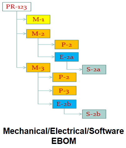 The EBOM typically contains purchase parts and make parts. The purchased parts are sourced based on their specification, and you might have a single source in the beginning. The make parts are entirely under your engineering control, and you define where they are produced and by whom. For the rest, the EBOM might have functional groupings of modules and subassemblies that are defined for reuse by engineering.
 Note: An EBOM is the place where multidisciplinary collaboration comes together. This post mainly deals with the mechanical part (as we are looking at the past)
Note: An EBOM can contain multiple valid configurations which you can filter based on a customer or market-specific demand. In this case, we talk about a Configured EBOM or a 150 % EBOM.
The MBOM
 The MBOM represents the way the unique product is going to be manufactured. This means the MBOM-structure will represent the manufacturing steps. For each EBOM-purchase-part, the approved manufacturer for that plant needs to be selected. For each make-part in the EBOM, if made in this plant per customer order, the EBOM parts need to be resolved by one or more manufacturing steps combined with purchased materials.
Let us look at some examples:
The flat MBOM
Some companies do not have real machinery anymore in their plants, the product they deliver to the market is only assembled at the best financial location. This means that all MBOM-parts should arrive at the shop floor to be assembled there. As an example, we have plant A below.
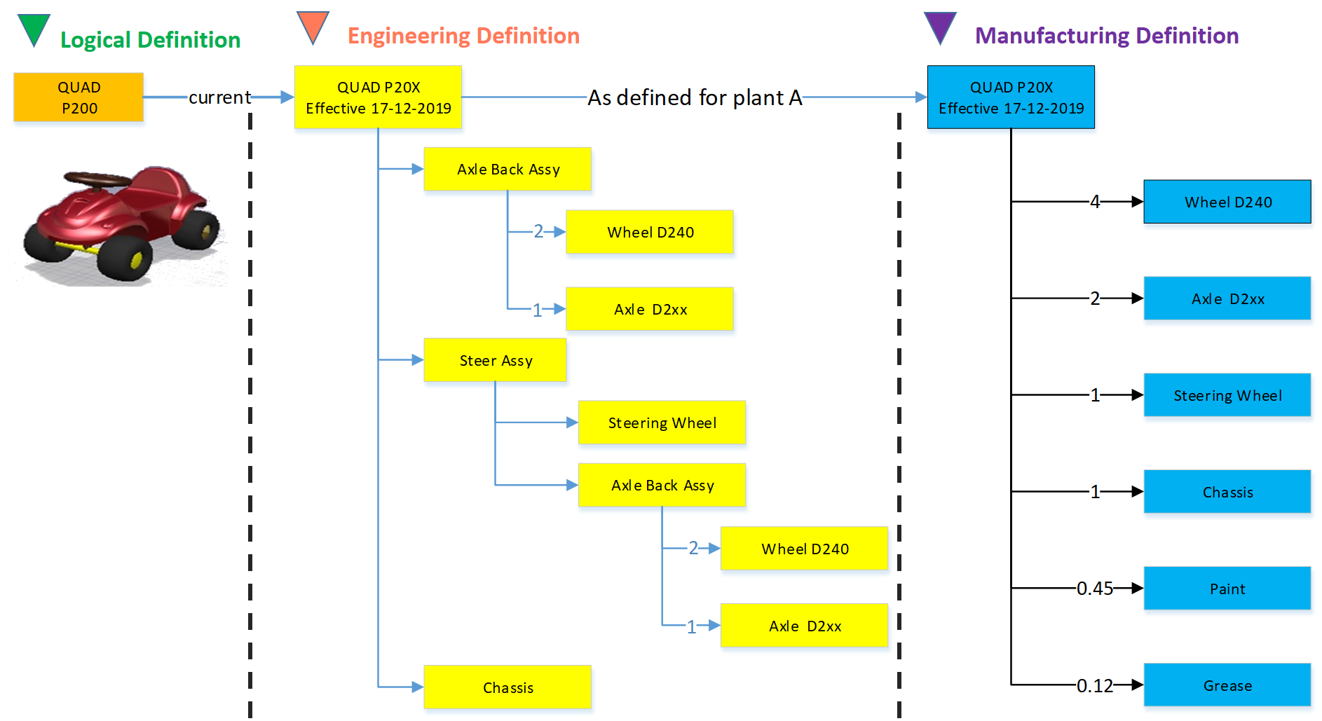
Of course, this is a simplified version to illustrate the basics of the MBOM. The flat MBOM only makes sense if the product is straightforward to assemble. Based on the engineering specifications, the assembly drawing(s) people on the shop floor will know what to do.
The engineering definition specifies that the chassis needs to be painted, and fitting the axles requires grease. These quantities are not visible in the EBOM; they will appear in the MBOM. The quantities and the unit of measure are, of course, relevant here.
Note: The exact quantities for paint and grease might be adjusted in the MBOM when a series of Squads have been manufactured.
The MBOM and Bill of Process
Most of the time, a product is manufactured in several process steps. For that reason, the MBOM is closely related to the Bill of Process or the Routing definitions. The image below illustrates the relationship between an MBOM and the operations in a plant.
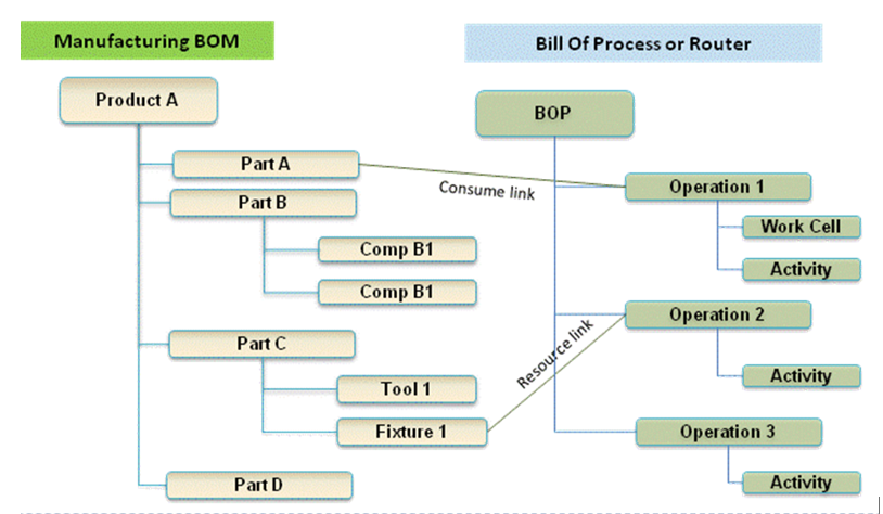
If we continue with our example of the Squad, let us now assume that the wheels and the axle are joined together in a work cell. In addition, the chassis is painted in a separate cell. The MBOM would look like the image below:

In the image, we see that the same Engineering definition now results in a different MBOM. A company can change the MBOM when optimizing the production, without affecting the engineering definition. In this MBOM, the Axle assembly might also be used in other squads manufactured by the company.
The MBOM and purchased parts
 In the previous example, all components for the Squad were manufactured by the same company with the option to produce in Plant A or in Plant B. Now imagine the company also has a plant C in a location where they cannot produce the wheels and axle assembly. Therefore plant C has to “purchase” the Wheel-Axle assembly, and lucky for them plant B is selling the Wheel+Axle assembly to the market as a product.
The MBOM for plant C would look like the image below:
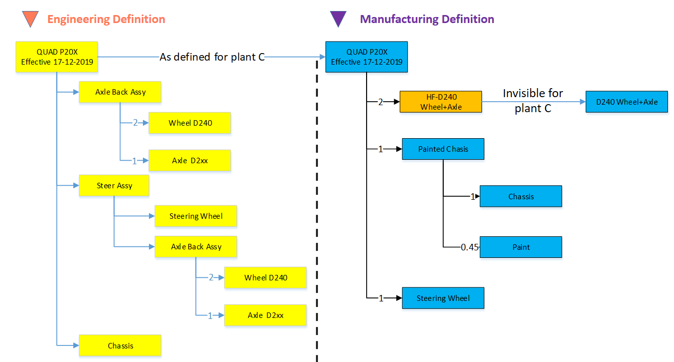
For Plant C, they will order the right amount of the Wheel+Axle product, according to its specifications (HF-D240). How the Wheel+Axle product is manufactured is invisible for Plant C, the only point to check is if the Wheel+Axle product complies with the Engineering Definition and if its purchase price is within the target price range.
Why this simple EBOM-MBOM story?
 For those always that have been active in the engineering domain, a better understanding of the information flow downstream to manufacturing is crucial. Historically this flow of information has been linear – and in many companies, it is still the fact. The main reason for that lies in the fact that engineering had their own system (PDM or PLM), and manufacturing has their own system (ERP).
Engineers did their best to provide the best engineering specification and release the data to ERP. In the early days, as discussed in Part 4, the engineering specification was most of the time based on a kind of hybrid BOM containing engineering and manufacturing parts already defined.
 Next, manufacturing engineering uses the engineering specifications to define the manufacturing BOM in the ERP system. Based on the drawings and parts list, they create a preferred manufacturing process (MBOM and BOP) – most of the time, a manual process. Despite the effort done by engineering, there might be a need to change the product. A different shape or dimension make manufacturing more efficient or done with existing tooling. This means an iteration, which causes delays and higher engineering costs.
The first optimization invented was the PDM-ERP interface to reduce the manual work and introduction of typos/misunderstanding of data. This topic was “hot” between 2000 and 2010, and I visited many SmarTeam customers and implementers to learn and later explain that this is a mission impossible. The picture below says it all.
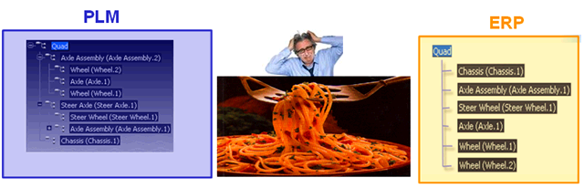
We have an engineering BOM (with related drawings). Through an interface, this EBOM will be restructured into a manufacturing BOM, thanks to all kinds of “clever” programming based on particular attributes. Discussed in Part 3
 The result, however, was that the interface was never covering all situations and became the most expensive part of the implementation.
Good business for the implementing companies, bad for the perception of PDM/PLM.
The lesson learned from all these situations: If you have a PLM-system that can support both the EBOM and MBOM in the same environment, you do not need this complex interface anymore. You can still use some automation to move from an EBOM to an MBOM.
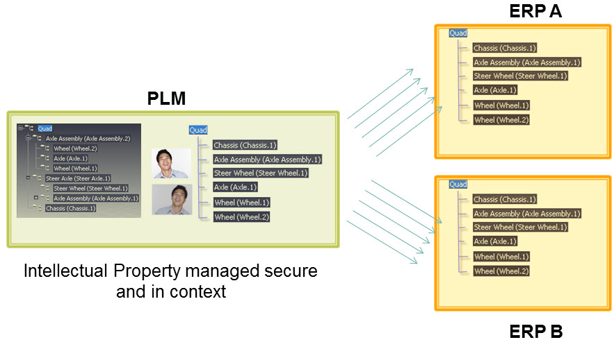
However, three essential benefits come from this approach
- Working in a single environment allows manufacturing engineers to work directly in the context of the EBOM, proposing changes to engineering in the same environment and perform manual restructuring on the MBOM as programming logic does not exist. Still, compare tools will ensure all EBOM-parts are resolved in the manufacturing definition.
- All product Intellectual Property is now managed in a single environment. There is no scattered product information residing in local ERP-systems. When companies moved towards multiple plants for manufacturing, there was the need for a centralized generic MBOM to be resolved for the local plant (local suppliers / local plant conditions). Having the generic MBOM and Bill of Process in PLM was the solution.
- When engineers and manufacturing engineers work in the same environment, manufacturing engineering can start earlier with the manufacturing process definition, providing early feedback to engineering even when the engineering specification has not been released. This approach allows real concurrent engineering, reducing time to market and cost significantly
Conclusion
Again 1600 words this time. We are now at the stage that connecting the EBOM and the MBOM in PLM has become a best practice in most standard PLM-systems. If implemented correctly, the interface to ERP is no longer on the critical path – the technology never has been the limitation – it is all about methodology.
Next time a little bit more on advanced EBOM/MBOM interactions
In this post in the series Learning from the past to understand the future, I want to leave the 3D CAD structures behind. But before doing so, I want to mention some of the lessons learned:
![]() In Part 1: “Intelligent” drawing numbers were the source for “intelligent” part numbers as often there was a one-to-one relationship between the drawing and the part(s) on a drawing.
In Part 1: “Intelligent” drawing numbers were the source for “intelligent” part numbers as often there was a one-to-one relationship between the drawing and the part(s) on a drawing.
 In Part 2: 3D CAD has been introduced in the automotive and aerospace industry due to process optimization, where a 3D CAD environment created better collaboration possibilities (DMU). The introduction of 3D CAD in the mid-market was different. Here 3D CAD is used as an engineering tool, not changing any processes.
The complexity grew because also file names needed to be managed, introducing the need for PDM-systems.
![]() In Part 3: we discussed the challenges of working with file-based 3D CAD structures. The versioning problem with check-in/check-out of structure in particular in the case of data reuse. Here the best practice was introduced to have physical parts with a different lifecycle than 3D CAD parts and assemblies.
In Part 3: we discussed the challenges of working with file-based 3D CAD structures. The versioning problem with check-in/check-out of structure in particular in the case of data reuse. Here the best practice was introduced to have physical parts with a different lifecycle than 3D CAD parts and assemblies.
Now engineers need to create valid configurations based on links between the physical part and the 3D/2D object. This requires a PDM-system with BOM and CAD-files as standard information objects.
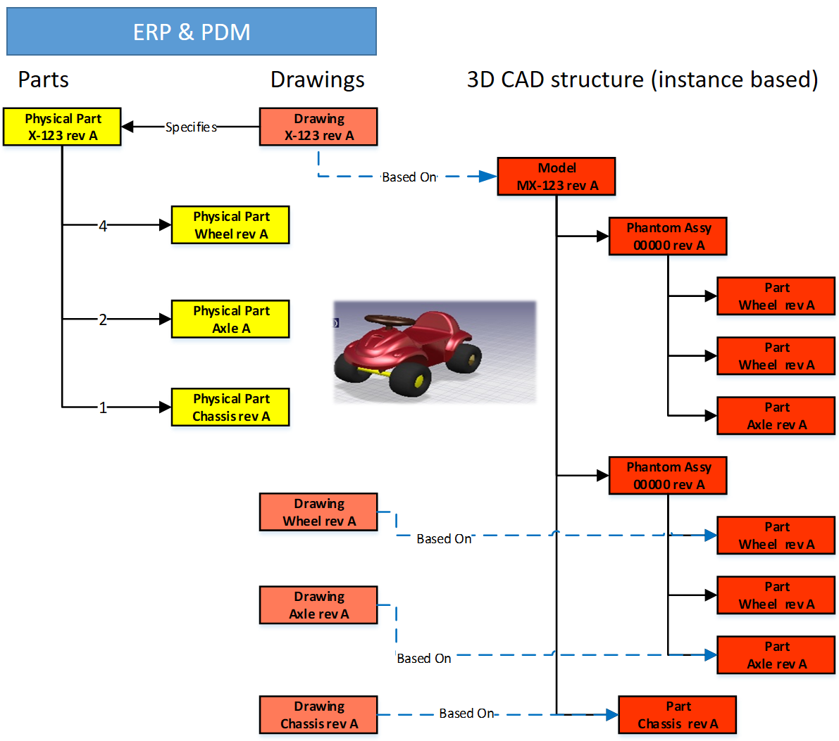 In Part 4: we discussed the relations between the BOM and 3D CAD structures without neglecting the fact the 2D Drawing is still the primary legal information carrier for manufacturing/suppliers. The point discussed in this post was the fact that most companies used a kind of ETO-approach. Starting from the 3D CAD-system, adding sometimes manufacturing parts in this structure, to generate a BOM that can be served as input for the ERP-system.
I want to follow up from the last conclusion:
Changing from ETO to CTO requires modularity and a BOM-driven approach. Starting from a 3D CAD-structure can still be done for the lowest levels – the modules, the options. In a configure to order process, it might not be relevant anymore to create a full 3D-representation of the product.
Starting from a conceptual structure
 Most companies that deliver products to the market do not start from scratch, as we discussed. They will start from either copying an existing product definition (not recommend) or trying to manage the differences between them, meanwhile keeping shared components under revision control.
 This cannot be done based on 3D CAD-structures anymore. At that time (we are in the early 2000s) in the mid-market, the PDM-system was used to manage these structures, in particular, they used the BOM-capabilities.
The BOM-structure was often called the EBOM, as engineers were defining the EBOM. But is it really an EBOM? Let us have a look wat defines an EBOM.
What characterizes an EBOM?
There are many personal definitions of what is considered as an EBOM. Also, the Wiki-definition here does not help us a lot. So here is my personal 2004 definition:
- The EBOM reflects the engineering view of a product and, therefore, can have a logical structure of assemblies and subassemblies based on functionality, modularity, and standardization.
- The EBOM is a part structure specifying a product from its design intent, specifying parts, materials, tolerances, finishing.
- The EBOM-structure is allowing multidisciplinary teams to work together on a joint definition of the product
The picture below illustrates the above definition.
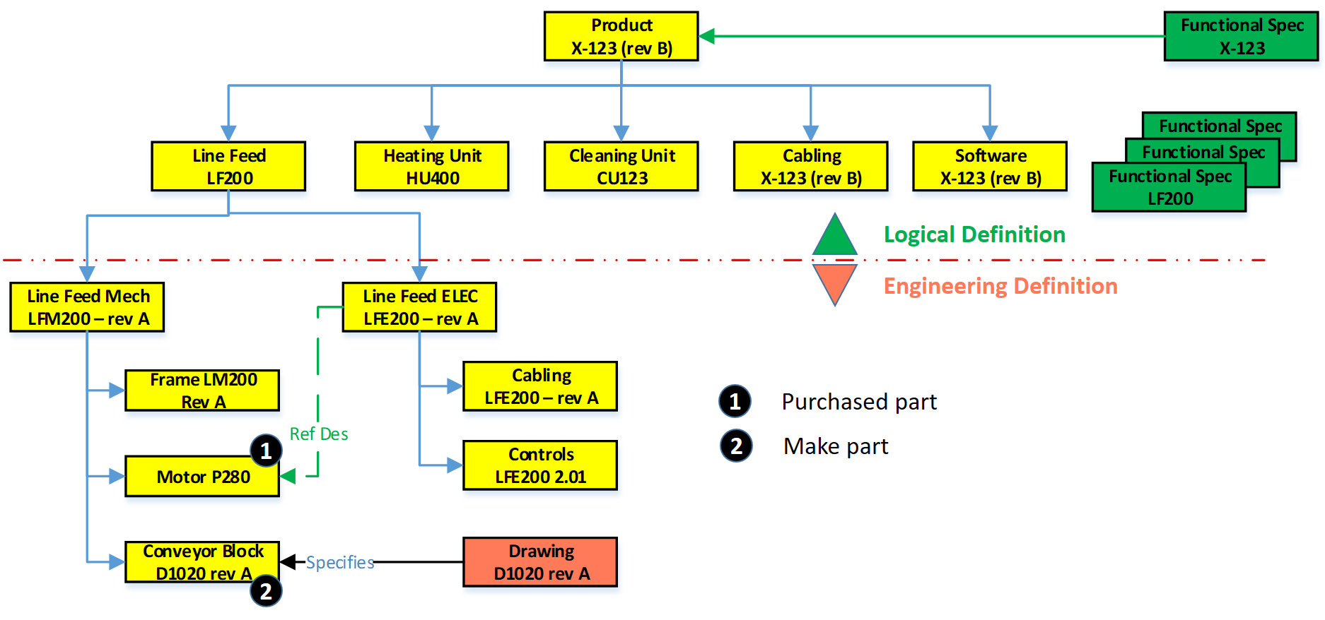
In this EBOM-structure, we see that the first two levels actually are more a logical division of functional groups, either as units, product/discipline-specific definitions (cabling/software). These components should not be in the EBOM if you have support for logical structures in your PLM-environment. However, in 2004 – PLM was not that mature in the mid-market, and this approach was often chosen.
If we look at the Line Feed module, which could also be used in other products, there is the typical mechanical definition and in parallel the electrical definition. Having them inside a single EBOM gives the advantage of being able to do a “where-used” and status/impact-analysis.
1 – Purchased parts
 Motor P280 is an interesting EBOM-part to consider. This motor is required; however, in an EBOM, you should not specify the supplier part number directly. As supplier part availability and preference will change over time, you do not want to revise the EBOM every time a supplier part gets changed.
 Therefore, the Motor P280 should have an internal part number in the EBOM. Next, it will be engineering that specifies which motors fulfill the need for Motor P280. Preferably they will create an Approved Manufacturing List for this motor to give manufacturing/purchasing the flexibility to decide per order where to purchase the motor and from which supplier.
The relation between the Approved Manufacturing List and the Approved Vendor List is shown in the diagram above.
![]() Or follow the link to this image to read more in Arena’s glossary. In particular, for electronic components, this concept is needed as high-level specifications for electronic parts might be the same.
Or follow the link to this image to read more in Arena’s glossary. In particular, for electronic components, this concept is needed as high-level specifications for electronic parts might be the same.
However, the details (tolerances/environment) can be decisive, which component is allowed. Besides, due to the relatively short lifecycle of electronic components, the EBOM needs to be designed in such a manner to anticipate changes in suppliers.
 You can only benefit from this approach if, from the beginning of your designs, there are no supplier-specific parts in your EBOM. For Engineering, to Order companies that want to become more Build to Order, this is a challenging but critical point to consider.
Note: The functional characteristics for the motor will come from the electrical definition, and through a reference designator, we create the link between the functional definition and the physical implementation in the product.
2 – Make Parts
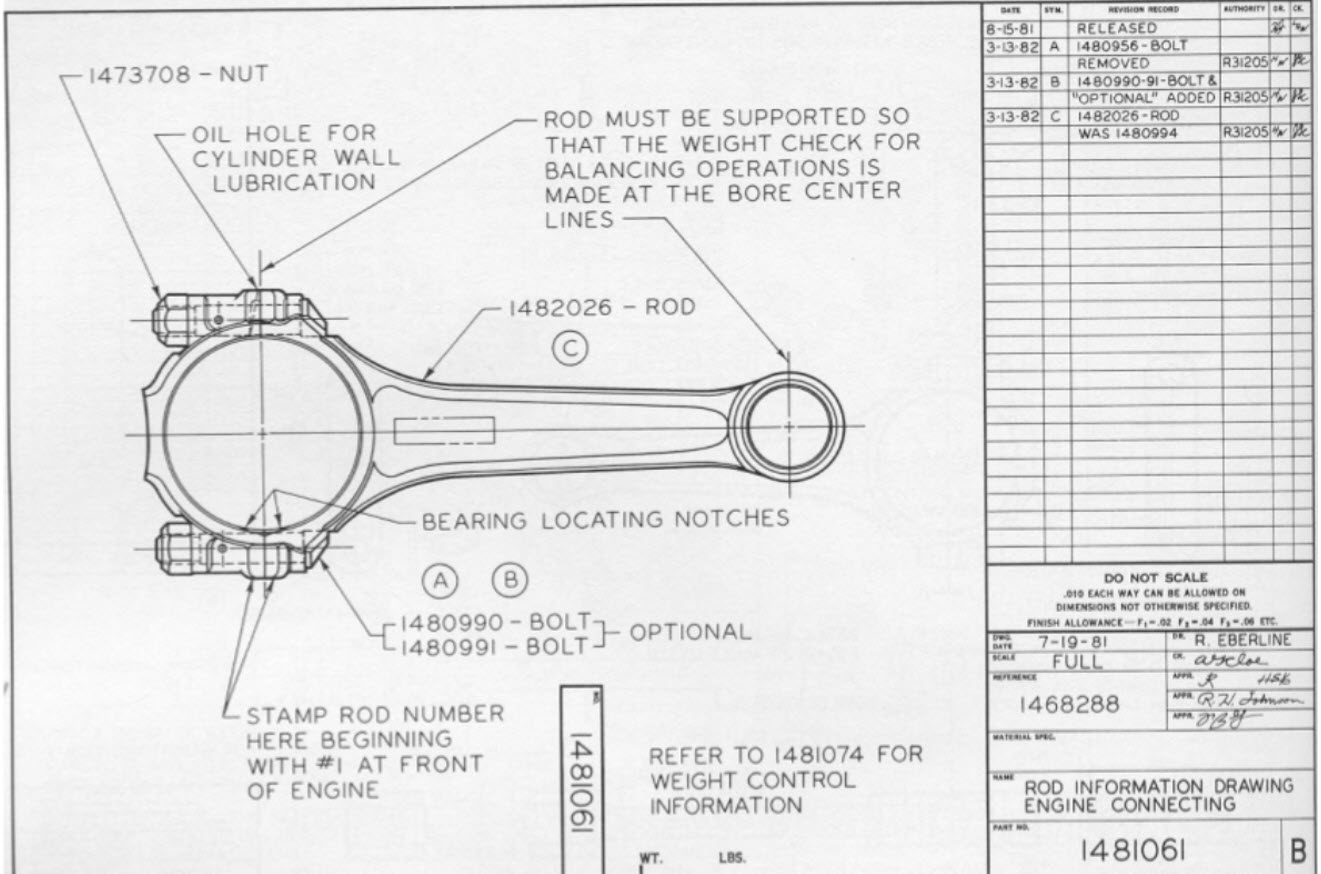 Secondly, if we look to the conveyor block D1020 rev A, this block is a make part, with probable a whole assembly of parts below it. As it is a make part, there is at least an assembly drawing and, more likely, a related technical data package linked to D1020 rev A. Make parts still carry a revision as here the Form-Fit-Function discussion can be used when implementing a change of the part.
Note: I used for the final assembly drawing the same number scheme as this is how most companies work. However, in my previous post, I described that if you have a PDM-system in place, the numbering can be different. Maintaining the relations between a part and the related drawing is, in this case, crucial.
The Configured EBOM
 The image on the left, we used to illustrate the typical mid-market EBOM in a PDM-system, will become more complicated if we also add options and variants to the EBOM. I assume you know the difference between a variant and an option.
In this case, the EBOM the definition for the full product range. Actually, the top part of the EBOM does not exist as an instance. It is the placeholder to select a resolved EBOM for a specific product configuration. For the ease of use, I have simplified the initial diagram, now zooming in on variants and options, apologizing for my artistic capabilities as the purpose of a blog is different from a book.
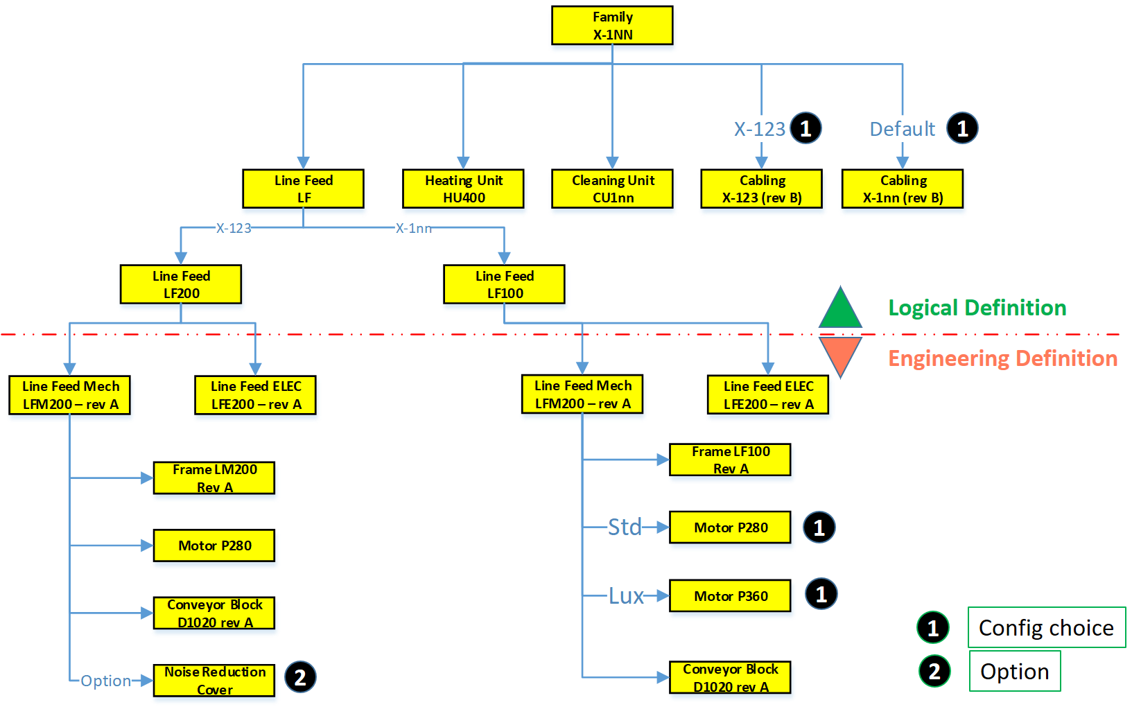
If we look at the diagram, this configured structure contains variants and options.
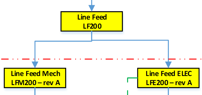 First, on the logical definition, we see a new grouping. There are two types of Line Feed available, one specific for the X-123 and a later, more generic designed LF100, suitable for all X-1nn variants.
As the LF100 is more generic designed, the customer can select between two motors, the standard P280 and the more advanced version P360, with better service capabilities.
![]() For the Line Feed LF200, there is an option to order a Noise Reduction Cover. It was sold once to an existing customer, and as the cover fits all X-123, it has been linked here as an option to the X-123 definition. So, the customer solution with the Noise Reduction Cover does not have an isolated, copied structure in the EBOM.
For the Line Feed LF200, there is an option to order a Noise Reduction Cover. It was sold once to an existing customer, and as the cover fits all X-123, it has been linked here as an option to the X-123 definition. So, the customer solution with the Noise Reduction Cover does not have an isolated, copied structure in the EBOM.
Also, in the Logical Structure, we see there is a cabling definition for the X-123 or the default cabling set for all other products.
 The diagram illustrates what many mid-market companies have been doing more or less in their PDM-system to avoid copying of EBOM structures per customer order.
It is an example of where a tool (the PDM-system) is slowly abused for administrative reasons. Let me explain why.
The link between Products and (E)BOMs
If we look at the upper part of the configured EBOM structure, this is a logical product definition. Or to say it in different words, it is a portfolio definition, which products and modules a company can sell to the market. Some of the grouping of the portfolio is purely based on business reasons, which products and options do we want to sell.

In most companies, the product portfolio is managed in (marketing) documents without a direct connection to the engineering world. However, we will see in an upcoming post, this relation is crucial for a digital enterprise. Meanwhile, look at on old blog post: Products, BOMs and Parts if you want to be faster
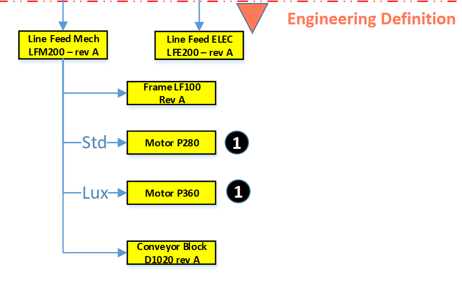 The Engineering definition below the red dashed line is a real EBOM, representing the engineering definition of a system, a module, or a component. When these systems and modules are defined in a single structure that can be filtered based on selection criteria, we talk about a Configured EBOM or sometimes a 150 % EBOM.
Each of the components in the configured EBOM can have a related 3D CAD structure or specification that can be developed traditionally.
The result of a resolved EBOM is a variant that can be delivered to the customer. In this EBOM-driven approach, there is not always a full 3D-representation of the customer product.
![]() Again, size (1500+) words make me stop this story, where next time we will go from product to EBOM and introduce the need for an MBOM in specific industries.
Again, size (1500+) words make me stop this story, where next time we will go from product to EBOM and introduce the need for an MBOM in specific industries.
Conclusion
A pure EBOM only specifies a product and contains all relevant information in context – designs & specifications. The EBOM should not be mixed or confused with a logical grouping, belonging to a portfolio definition (even if the system allows you to do it)
On my previous post shared on LinkedIn Ilan Madjar, a long-time PLM colleague reacted with the following point (full thread here)

Ilan is pointing to the right challenge in many companies. Changing the way you work is though exercise and requires a good understanding, vision, and execution to move forward. Do not trust the tool to work for you – it is about human understanding and process re-engineering to be more efficient. And if you do not practice this on the basic PDM-level as discussed so far, imagine the impossibility of going through a digital transformation.
 Last time in the series Learning from the past to understand the future, we zoomed in on how the 3D CAD-structure in the mid-market had to evolve. In a typical Engineering To Order (ETO) scenario, it makes sense to extract from the 3D CAD-structure a BOM-structure to collect all the individual parts that are needed for manufacturing. Combined with the drawings generated based on the 3D CAD assemblies/parts, the complete manufacturing information could be provided. Let’s have a look.
The BOM in ERP (part 1)
To understand what most mid-market companies have been doing, I created the image below. When you click on it, you will have an enlarged version.
Note: for educational purposes an extremely simplified example
There is a lot to explain here.
First, on the right we see the 3D CAD assembly, two phantom assemblies, grouping the wheels and the axle. And at the end, the individual parts, i.e. chassis, axle, and wheel. The 3D CAD-structure is an instance-based structure; therefore, there are no quantities in the structure (all quantity 1)
For the individual parts, there are drawings. Also, for the product, we have an assembly drawing. The drawings are essential as we want to have them in the ERP-system for manufacturing.
Finally, the physical parts, now with a different ID than the drawing as we learned this one-to-one relation created a lot of extra work. The physical parts are often called Items or Materials (SAP naming). Unfortunately, for engineering, there is a different meaning behind Materials. Still, SAP’s data model was not built with an engineering mindset.
The physical part structure, which we call the BOM contains quantities. Most PDM-CAD-integrations can filter out phantom assemblies and summarize the parts on the same level
 I am still reluctant to call the Part-structure an EBOM as the design of the product has been mainly focusing on extracting manufacturing information, parts, and drawings.
The BOM in ERP (part 2)
In customized PDM-implementations, some implementers created an interface from the BOM-structure to ERP, so the ERP-system would have the basic definition of the parts and a copy of the relevant drawings.
Now manufacturing could create the manufacturing definition without the need to go into the PDM-system.
Some “clever” – Dick Bourke would say “smart – therefore lazy” – proposed to “draw” also manufacturing entities in the 3D CAD-structure, so the PDM-CAD-interface would automatically deliver manufacturing parts too inside the ERP. In the example below, we added paint for the body and grease needed for the axels.
Although “smart, a new problem was introduced here – the 3D CAD-structure, instance-based, always has quantities 1. The extracted BOM would have rounded numbers when considering design parts. Now the grease comes with an estimate of 0.025 kg, assuming quantities are based on SI-units. We could also add other manufacturing information to this BOM, like 0.3-liter paint. Anyway, the result would look like below:
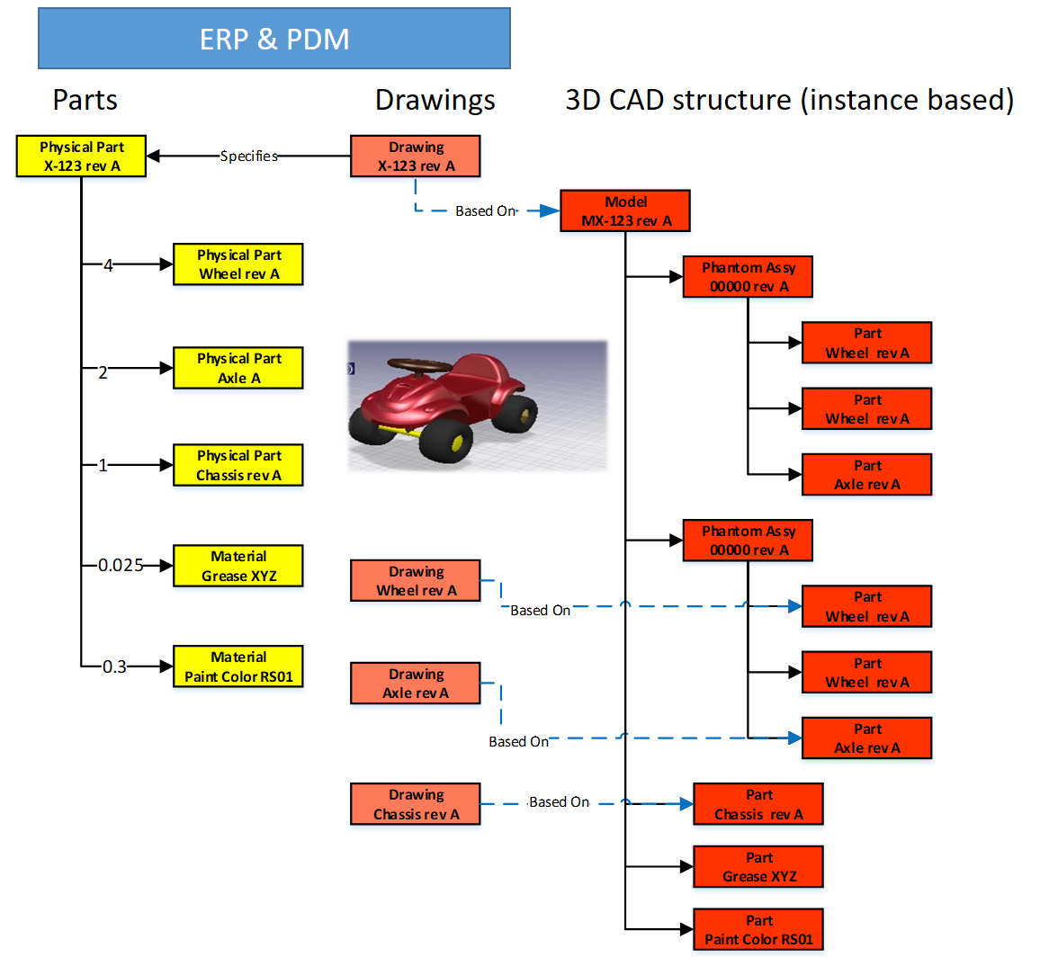
Important to notice from the diagram here: There are placeholders for grease and paint “drawn” in the 3D CAD-structure – parts without a geometrical definition and, therefore, not having an associated drawing. However, these parts have a material specification, and therefore in the BOM-structure, they appear as Materials.
Next in the BOM-structure, the engineers would enter the expected/required quantity – which is no longer a rounded number.
 At this stage, you cannot call the BOM on the left an EBOM. It is a kind of hybrid structure, combining engineering and manufacturing data. A type of BOM we discover a lot in companies that started with a type of ETO-product.
The ETO-product
 Many companies that developed specialized machinery have started with a base product, from where they developed the custom solution – their IP. Next, with more and more customers, the original solution was extended by creating either new or changed capabilities.
I worked a lot with companies that moved to the full definition of their products in 3D CAD, creating a correct 3D CAD-structure per customer order. Instead of creating new BOM variants, companies were often tempted/forced to make the configuration inside the 3D CAD-model.

Every time one of the configurations of the part would change, or a new configuration was added, the file has to be revised.
 And if the change was at level five of a 3D CAD-structure, many assembly files needed to be updated. The versioning problem illustrates the challenge of managing configurations inside a 3D CAD-file, meanwhile creating complexity for the PDM/PLM-system.
Last week Tech-Clarity published the highlights of their survey: Bringing Custom-Engineered Products to Market with a link to the full report, sponsored by Propel.
 As you can imagine, this survey is more about PLM collaboration, breaking down the silos and acting agile. Unfortunately, the report does not expose required methodologies, like modularity and “common sense” engineering practices that we discuss here. Still worthwhile to read as the report addresses precisely the type of companies I am referring too here.
If we look at the methodology of custom-engineered products, let us look at how their “best practice” from the past is blocking the future.
When a new customer request is coming in, sales engineering is looking for the best match of delivered products. Hopefully, 80-90 % remains the same, and engineering has to focus only on the differences.
 First, the best-match 3D CAD-structure is copied to a new project. As you can see most 3D CAD-systems provide the functionality to create a derived structure from an original 3D CAD-structure. From there, a traditional ETO-process starts as described at the beginning of this post. We complete the 3D CAD-structure with manufacturing in mind, generate the BOM and drawings, and we can deliver. In the case of purchase parts, the generated BOM often contains already the supplier part number in the 3D CAD-structure as we are focusing on this single delivery.
The disadvantage of this approach that in theory, we have to check if the structure that we reused is really the best so far, otherwise we introduce errors again.
 The second disadvantage is that if one supplier part in the structure becomes obsolete and needs to be revised, the company has to go through all the 3D CAD-structures to fix it.
Also, having supplier parts in the 3D CAD-structure makes it more difficult to standardize, as the chosen supplier part matched the criteria for that customer at that time. Will it match the criteria also in other situations?
From ETO to BTO to CTO
Many companies that started with custom-engineered products, the ETO-approach, want to move towards a Configure To Order (CTO) approach – or if not possible at least Build To Order (BTO). More reuse, less risk, instead of creating every time a new solution for the next customer, as discussed before.
This is not a mission impossible; however, often, I have seen that companies do not set the right priorities to move towards a configure to order environment. There are a few changes needed to become a configure to order company (if possible):
- Analyze your solution and define modules and options. Instead of defining a full solution, the target now is to discover a commonality between the various solutions. Based on commonality, define modules and options in such a manner that they can be used in different situations. Crucial for these modules is that there is a standard interface to the rest of the product. Every company needs to master this specific methodology for their products
- Start defining products from a logical structure, defining how products, modules and options are compatible and which combinations are allowed (or preferred). For companies that are not familiar with logical structure, often a configured EBOM is used to define the solutions. Not the optimal way; however, this was the first approach most companies took ten years ago. I will explain the configured EBOM below.
- A product definition and its modules now should start from a real EBOM, not containing manufacturing characteristics. The EBOM should represent the logical manner of how a product is defined. You will notice this type of EBOM might be only 2 – 3 levels deep. At the lowest level, you have the modules that have their own lifecycle and isolated definition.
- You should no longer use supplier part numbers in your EBOMs. As the engineering definition of a module or option should not depend over time from a single supplier. We will discuss in the next post the relation between EBOM parts and the Approved Manufacturer List (AML)
To conclude for today
Changing from ETO to CTO requires modularity and a BOM-driven approach. Starting from a 3D CAD-structure can still be done for the lowest levels – the modules, the options. In a configure to order process, it might not be relevant anymore to create a full 3D-representation of the product.
However, when we look forward, it would be greatly beneficial to have the 3D-representation of every specific solution delivered. This is where concepts as augmented/virtual reality and digital twin come in.
Next time more on the BOM-structures – as we have just touched the upcoming of the EBOM – enough to clarify next week(s).

Interesting reflection, Jos. In my experience, the situation you describe is very recognizable. At the company where I work, sustainability…
[…] (The following post from PLM Green Global Alliance cofounder Jos Voskuil first appeared in his European PLM-focused blog HERE.) […]
[…] recent discussions in the PLM ecosystem, including PSC Transition Technologies (EcoPLM), CIMPA PLM services (LCA), and the Design for…
Jos, all interesting and relevant. There are additional elements to be mentioned and Ontologies seem to be one of the…
Jos, as usual, you've provided a buffet of "food for thought". Where do you see AI being trained by a…