
 Over the last month, I have been actively engaged in the field; however, unfortunately, I have not been able to respond to all the interesting and sometimes humorous posts in my LinkedIn stream.
The fun started with a post from Oleg referring to a so-called BOM battle presented at Autodesk University by Gus Quade.
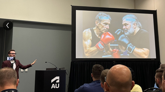
The image seems fake; however, the muscle power behind the BOM players looks real.
Prof. Dr. Jörg Fischer, also pictured, is advocating for rethinking PLM and BOM structures, and I share his discomfort.
Prof. Fischer wrote recently: “Forget everything you know about EBOM and MBOM. CTO+ is rewriting the rules of PLM. “
I am not a CTO expert, but I can grasp the underlying concepts and understand why it is closely associated with SAP. It aligns with the ultimate goal of maintaining a continuous flow of information throughout the company, with ERP (SAP?) at its core.
My question is, how far are we from that option?
Current PLM implementations often focus on a linear process and data collection from left to right, as illustrated in the old Aras image below. I call this the coordinated approach.

 During the recent Dutch PLM platform meeting, we also discussed the potential need for an eBOM, mBOM, and potentially the sBOM. A topic many mid-sized manufacturing companies have not mastered or implemented yet – illustrating the friction in current businesses.
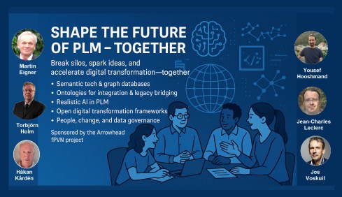
Meanwhile, we discuss agentic AI, the need for data quality, ontologies and graph databases. Take a look at the upcoming workshop on the Future of PLM, scheduled for November 4th in Paris, which serves as a precursor to the PLM Roadmap/PDT Europe 2025 conference on November 5th and 6th.
The reality in the field and future capabilities seem to be so far apart, which made me think about what the next step is after BOM management to move towards the future.
The evolution of the BOM
For those active in PLM, this brief theory ensures we share a common understanding of BOMs.
Level 0: In the beginning, there was THE BOM.
 Initially, the Bill of Materials (BOM) existed only in ERP systems to support manufacturing. Together with the Bill of Process (BOP), it formed the heart of production execution. Without a BOM in ERP, product delivery would fail.
Level 1: Then came a new BOM from CAD.
 With the rise of PDM systems and 3D CAD, another BOM emerged — reflecting the product’s design structure, including assemblies and parts. Often referred to as the CAD or engineering BOM, it frequently contained manufacturing details, such as supplier parts or consumables like paint and glue.
This hybrid BOM bridged engineering and manufacturing, linking CAD/PDM with ERP. Many machine manufacturers adopted this model, as each project was customer-specific and often involved reusing data by copying similar projects.
![]() Many industrial manufacturers still use this linear approach to deliver solutions to their customers.
Many industrial manufacturers still use this linear approach to deliver solutions to their customers.
Level 2: The real eBOM and mBOM arrived.
Later, companies began distinguishing between the engineering BOM (eBOM) and manufacturing BOM (mBOM), especially as engineering became centralized and manufacturing decentralized.

The eBOM represented the stable engineering definition, while the mBOM was derived locally, adapting parts to specific suppliers or production needs.
At the same time, many organizations aimed to evolve toward a Configure-to-Order (CTO) business model — a long-term aspiration in aligning engineering and manufacturing flexibility, as noted by Prof. Jörg Fischer in his CTO+ concept.
A side step: The impact of modularity
 Shifting from Engineer-to-Order (ETO) to Configure-to-Order (CTO) relies on adopting a modular product architecture. Modularity enables specific modules to remain stable while others evolve in response to ongoing innovation.
It’s not just about creating a 200% eBOM or 150% mBOM but about defining modules with their own lifecycles that may span multiple product platforms. Many companies still struggle to apply these principles, as seen in discussions within the North European Modularity (NEM) network.
See one of my reports: The week after the North European Modularity network meeting.
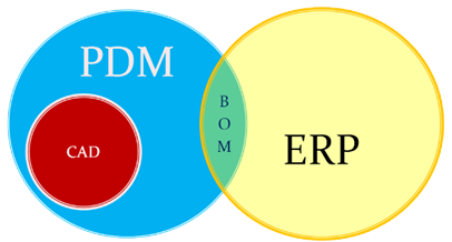
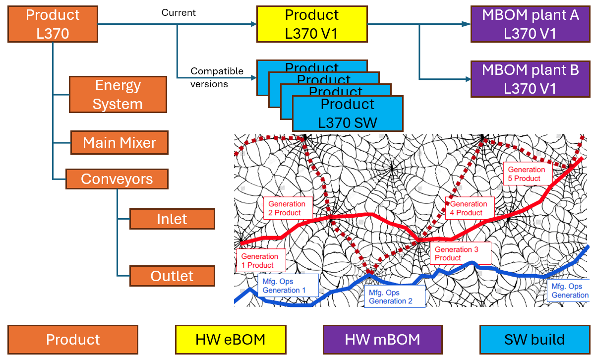
We remain here primarily in the xBOM mindset: the eBOM defines engineering specifications, while the mBOM defines the physical realization—specific to suppliers or production sites.
Level 3: Extending to the sBOM?
 To support service operations, the service BOM (sBOM) is introduced, managing serviceable parts and kits linked to the product. Managing service information in a connected manner adds complexity but also significant value, as the best margins often come from after-sales service.
Click on the image above to understand the relations between the eBOM, mBOM(s) and sBOM.
 However, is the sBOM the real solution or only a theme pushed by BOM/PLM vendors to keep everything within their system? So far, this represents a linear hardware delivery model, with BOM structures tied to local ERP systems.
For most hardware manufacturers, the story ends here—but when software and product updates become part of the service, the lifecycle story continues.
The next levels: Software and Product Services require more than a BOM
 As I mentioned earlier, during the Dutch PLM platform discussion, we had an interesting debate that began with the question of how to manage and service a product during operation. Here, we reach a new level of PLM – not only delivering products as efficiently as possible, but also maintaining them in the field – often for many years.
There were two themes we discussed:
- The product gets physical updates and upgrades – how can we manage this with the sBOM – challenges with BOM versions or revisions ( a legacy approach)
- The product functions based on software-driven behavior, and the software can be updated on demand – how can we manage this with the sBOM (a different lifecycle)
The conclusion and answer to these two questions were:
We cannot use the sBOM anymore for this; in both cases, you need an additional (infra)structure to keep track of changes over time, I call it the logical product structure or product architecture.
The Logical Product Structure
 Since 2008, I have been involved in Asset Lifecycle Management projects, explaining the complementary value of PLM methodology and concepts related to an MRO environment, particularly for managing significant assets, such as those in the nuclear plants industry.
Historically, the configuration management of a plant was a human effort undertaken by individuals with extensive intrinsic knowledge.
A nuclear plant is an asset with a very long lifecycle that requires regular upgrades and services, and where safety is the top priority. However, thanks to digitization and an aging workforce, there was also a need to embed these practices within a digital infrastructure.
What I learned is that the logical product structure, also known as the plant breakdown structure (PBS), became an essential structure for combining the as-designed and as-operated structures of the plant.
In the SmarTeam image below, the plant breakdown structure was represented by the tag structure.

Coming back to our industrial products in service, it is conceptually a similar approach, albeit that the safety drivers and business margins might make it less urgent. For a product, there can also be a logical product structure that represents the logical components and their connections.
The logical structure of a product remains stable over time; however, specific modules or capabilities may be required, while the physical implementation (mBOM) and engineering definition (eBOM) may evolve over time.
Additionally, all relevant service activities, including issues and operational and maintenance data, can be linked to the logical structure. The logical structure is also the structure used for a digital twin representation.
The logical product structure and software
The logical product structure is also where hardware and software meet. The software can be managed in an ALM environment and provides traceability to the product in service through the product structure.
Note: this is a very simplified version, as you can imagine, it looks more like a web of connected datasets – the top level shows the traceability between the various artifacts – HW and SW
Where is the product structure defined?
The product structure originates from a system architect, and it depends on the tools they are using, where it is defined – historically in a document, later in an Excel file – the coordinated approach.
In a modern data-driven environment, you can find the product structure in an MBSE environment and then connect to a PLM system – the federated and connected approach.
There are also PLM vendors that have the main MBSE data elements in their core data model, reducing the need for building connectivity between the main PLM and MBSE elements. In my experience, the “all-in-one” solutions still underperform in usability and completeness.
Conclusion
I wrote this post to raise awareness that a narrow focus on BOM structures can create a potential risk for the future. Changing business models, for example, the product-service system, require a data-driven infrastructure where both hardware and software artifacts need to be managed in context. Probably not in a single system but supported by a federated infrastructure with a mix of technologies. And I feel sorry that I could not write about a model-based enterprise at this time!
I am looking forward to discussing the future of PLM with a select group of thought leaders on November 4th in Paris, as a precursor to the upcoming PLM Roadmap/PDT Europe conference. For the workshop on November 4th, we almost reached our maximum size we can accommodate, but for the conference, there is still the option to join us.
Please review the agenda and join us for engaging and educational discussions if you can.
And if you are not tired of discussing PLM as a term, a system or a strategy – watch the recording of this unique collection of PLM voices moderated by Michael Finochario.

Leave a comment
Comments feed for this article